1 FUNDAMENTALS OF ONSHORE DRILLING
1.1 THE PRINCIPLE OF ROTARY DRILLING (Fig. 1.1, video 1)
The rotary method uses tricone-type toothed bits or one-piece bits such as diamond or PDC bits. While the bit is being rotated, a force is applied to it by a weight. The advantage is that a fluid can be pumped continuously through the bit, which is crushing the rock formation, and carry cuttings up out of the hole to the surface with the rising fluid flow.
It is the drill collars, screwed onto the bottom of the drill pipe assembly just above the bit, that provide the necessary weight. Drill collars, along with drill pipe and bit all make up the drill string, which is rotated by the rotary table and the kelly. The drill string component parts are hollow down the middle so that the drilling fluid can be circulated down to the bit. A fluid-tight rotary joint, the swivel, is located at the top of the kelly and provides a connection between the mud pump discharge line and the inside of the drill string. A hoisting systemic required supporting the weight of the drill string, lowering it into the hole and pulling it out. This is the function of the derrick, the hook and the draw works.
The drilling rig is complete with facilities to treat the drilling fluid when it gets back to the surface, a storage area for tubular goods, shelters and offices on the site.
In addition, when a well is being drilled it is regularly cased. It is lined with steel pipe, or casing, which is lowered into the hole under its own weight in smaller and smaller diameters as the hole gets deeper. The first length of pipe is run in as soon as the bit has drilled the surface formation and is then cemented in the hole. A casing housing is connected to the top of the surface casing. All the following lengths of pipe are hung on the casing housing and cemented at their base to the walls of the hole (Fig. 1.2).
After the first drilling phase is cased, drilling will be resumed with a bit with a diameter smaller than the inside diameter of the casing string that was run in and cemented. The deeper the borehole gets and the more casings are set in the well, the smaller the diameter of the bit must be.
The casing housing also serves to hold the safety equipment, such as blowout preventers.
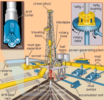 Fig. 1.1: Principles of Drilling Techniques
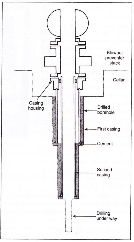 Fig. 1.2: Simplified Cross – Section of a Borehole
1.2 THE MAJOR OPERATIONS
1.2.1 Drilling (Fig. 1.3)
Though drilling is the basic operation, it is the one that requires the fewest number of people. The driller operates the draw works alone. The rotary table rotates and drives the drilling bit by means of the drill string and the kelly. The main control device is the brake lever. The driller controls and regulates the downward movement of the hook by putting on the brake. According to the principle of rotary drilling, bits are used at constant weight. The weight of everything that is suspended from the hook is constant and the driller knows this information by reading the weight on the hook when the bit is off bottom (Fig. 1.4).
The weight applied on the bit is the difference between the weight on the hook off bottom and on bottom.
This is the difference that the driller reads on the weight indicator (commonly called Martin Decker). He must keep it constant by lowering the kelly at the same speed as the rate of penetration of the bit.
The other two parameters, rotation and mud flow rate, are generally preset. The driller checks and adjusts the values depending on the program and mainly sees to it that the pump discharge pressure complies with the program and stays that way (video 2).
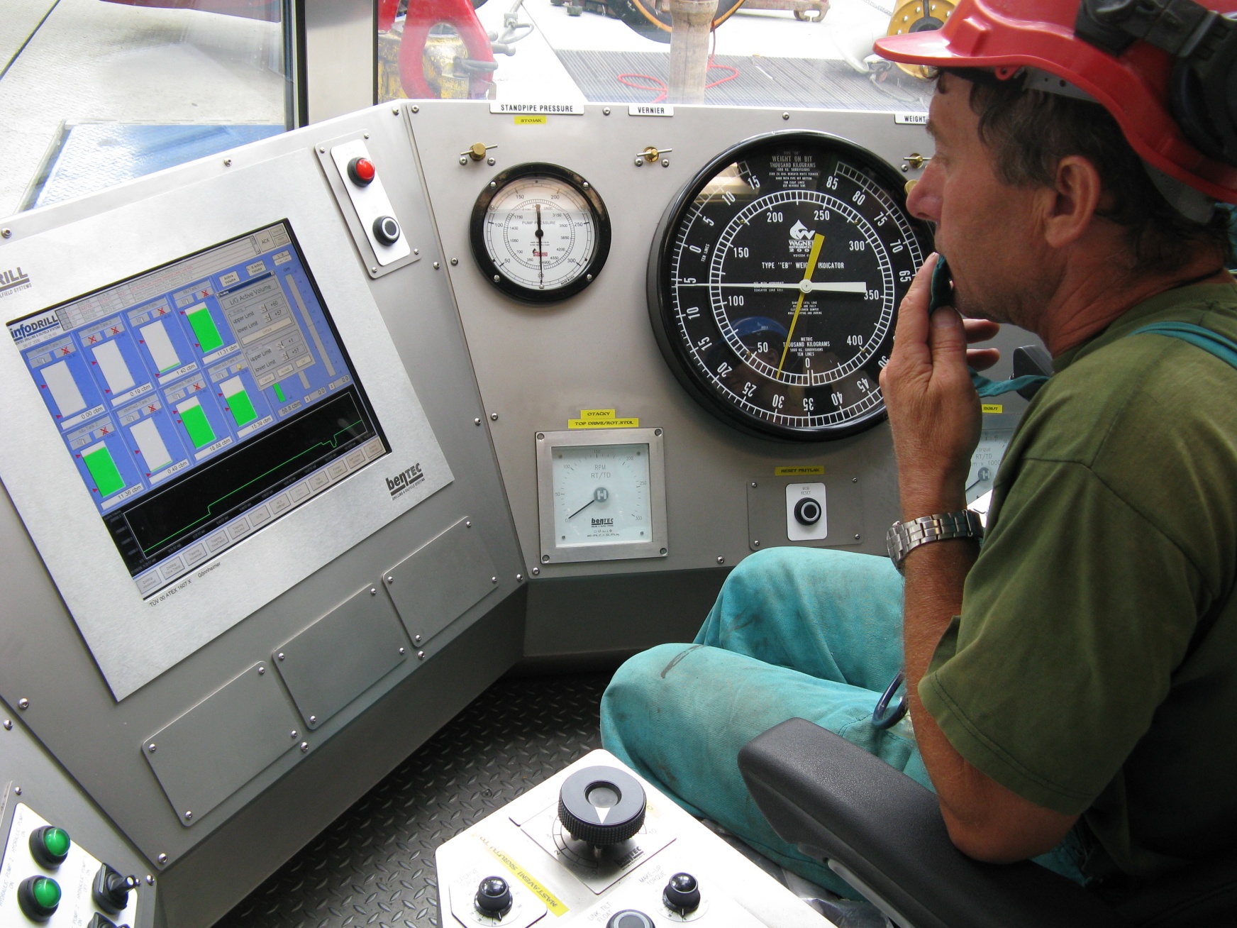 Fig. 1.3: The Driller´s Control Console
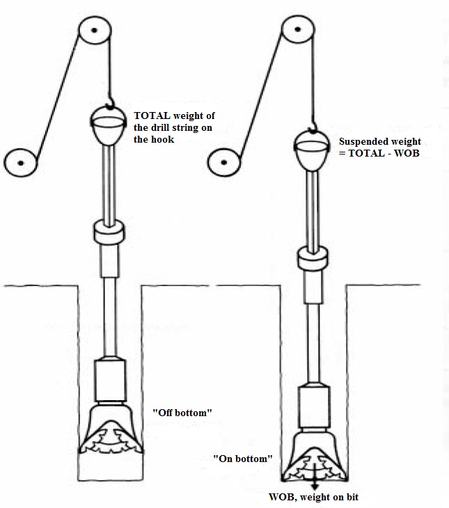 Fig. 1.4: Checking the Weight on the Bit
1.2.2 Adding drillpipe (video 3, video 4)
When the bit has drilled the equivalent of a length of pipe (30 ft), the drill string must be lengthened by screwing a new joint of drill pipe onto the bottom of the kelly. The sequence is illustrated in Figs. 1.5a, 1.5b, 1.5c and 1.5d:
- During drilling, the crew places a joint of pipe in a sheath, called the mousehole, located near the rotary table.
- The driller engages the draw works to hoist the drill string to the first length of drillpipe under the kelly. The crew puts the slips in place and the kelly can be unscrewed since the drill string is supported by the rotary table. Mud circulation has of course been stopped. In Fig. 1.5b, the crew screws the kelly to the box end of the length of drillpipe in the mousehole. Pipe is screwed and made up in the mousehole.
- The driller hoists the kelly and drillpipe with the drawworks (Fig. 1.5c). Once the new joint of pipe has been screwed and made up on the drill string, the driller resumes drilling fluid circulation.
- The crew places the kelly bushing back in the rotary table and drilling can be resumed (Fig. 1.5d).
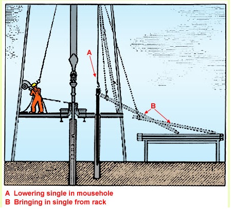 Fig. 1.5 a
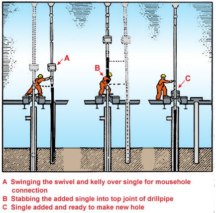 Fig. 1.5 b, c, d
1.2.3 The round trip (video 5, video 8)
When the bit is worn or when total borehole depth has been reached, all of the drill string must be pulled out of the hole to change bits or run in casing pipe.
The first step is to disconnect the swivel from the hook and place the kelly and the swivel – which is still connected to the mud pumps by the hose – in a sheath called the rathole (Fig. 1.6a).
The crew latches the elevator under the tool joint of the first length of drillpipe and the driller hoists the drill string to a height of three joints of pipe with the draw works.
The fourth length of pipe is clamped in the rotary table by the slips and the connection is unscrewed with the tongs (Fig. 1.6b). A stand of three lengths of pipe is then hanging from the elevator. The crew pushes the lower end of the stand so that is rests on the setback. Then the derrickman, who stands on the monkey board, unlatches the elevator, holds the stand and places the upper end of the stand in the pipe rack (Figs. 1.6c and 1.7).
The operation continues down to the drill collars that are also stacked vertically in threes.
The stand length depends on how high the derrick is. The largest rigs handle stands in threes, lightweight rigs in twos and the smallest ones can manage only singles. The running in or tripping in, operation is carried out in the same way.
During a round trip both rotation and circulation are at a standstill. If either is needed, the kelly is taken out of the rathole and screwed back onto the drill string.
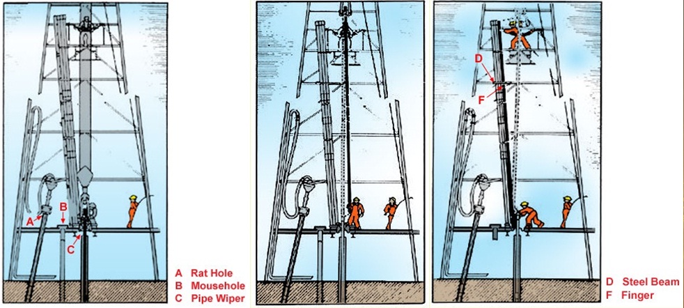 Fig. 1.6: Round Trip
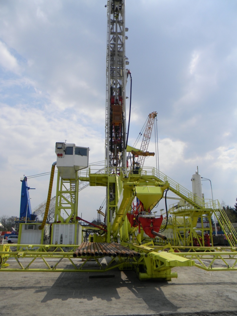 Fig. 1.7: Drilling Rig LOC 400 (Huisman comp.)
1.2.4 Casing (Fig. 1.8, video 6, video 7)
Once the borehole has been drilled to the depth planned for the current phase, the casing pipe is run into the well. The operation is hazardous because of the narrow clearance between the casing and the borehole, and since it is almost impossible to rotate the casing string. Casing pipe is run in singly joint by joint. Once it is run in, normal circulation (i.e. down the inside of the pipe) is used to pump cement into the annulus between the casing and the borehole wall.
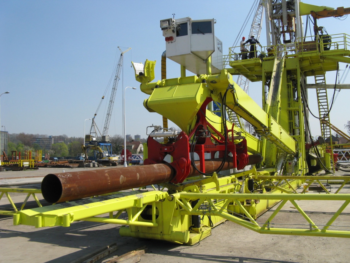 Fig. 1.8: Casing String
1.2.5 Installing the wellhead
When casing has been run into the well and cemented, a variety of hanging and sealing equipment must be installed on top of the well.
The operations are done manually when wellheads are above ground or above the surface of the sea offshore.
Wellhead equipment also accommodates the blowout preventers (BOP) that have a high-pressure system called kill line and choke line.
A series of pressure tests on the casing, hangers and BOP finalizes the installation. If everything complies with safety requirements, the following drilling phase can then commence.
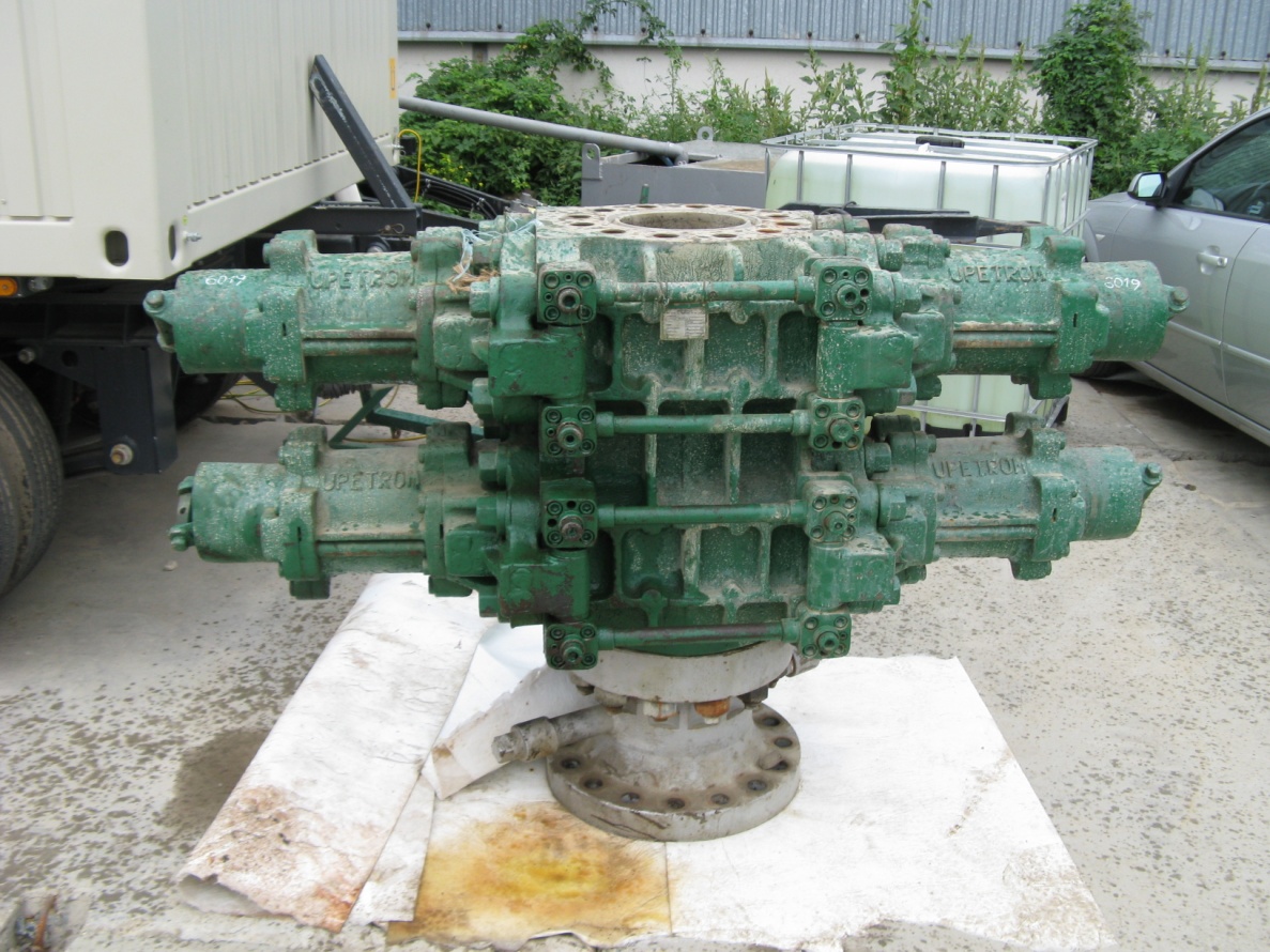 Fig. 1.9: Blowout Preventers (BOP)
1.2.6 Completion (video 1)
This is the final operation just after running in the last casing string (production casing). The production equipment is run into the well: packer, tubing, safety valve, etc. The connection between the producing formation and the well must often be enhanced by drilling, perforations, acidizing, fracturing, etc.
Though these operations are often performed by drillers, the techniques involved come under the heading of downhole production which is dealt with in another project.
The purpose of the following chapters is to describe as completely as possible the materials, equipment and operating techniques that are involved during drilling. This book aims to serve as an introduction to an operation that is more complex than it seems. The goal is to help the reader who is not a driller, but whose activity is related to drilling, understand the basics.
2 THE DRILLING RIG (video 1)
2.1 INTRODUCTION
Now that the principles of modern drilling methods have been discussed, the material resources, operating techniques and personnel required to drill the actual oilwell will be dealt with.
The drilling rig, or more comprehensively the well site, includes the following:
- production of primary energy,
- expendable product storage and warehousing,
- facilities for handling waste discharges,
- shelters,
- the derrick,
- the pumping facilities and tanks.
Figure 2.1 serves as a reminder and gives a schematic picture of rig functions: hoisting, pumping and rotation.
A drilling rig can be classified initially by its maximum drilling depth rating:
Lightweight rigs .......................................... 1,500 to 2,000 m
Intermediate rigs ......................................... 3,500 m
Heavyweight rigs ........................................ 6,000 m
Ultraheavy rigs ............................................ 8,000 to 10,000 m
Drilling depth capacity means weight on the hoisting hook, based on the weight of drill strings and casings.
On the basis of commonly acknowledged tripping times, the maximum power that the draw works will need to develop can be evaluated.
This is why when a drilling rig is due to be selected; the only thing of interest is the power rating of the draw works. This characteristic fits in with the depth rating and English speaking drillers even have a practical rule of the thumb for it: every 100 feet of borehole requires 10 horsepower (HP) at the draw works. For the rig categories listed above, this gives:
Lightweight rigs .......................................... 650 m
Intermediate rigs ......................................... 1300 m
Heavyweight rigs ........................................ 2000 m
Ultraheavy rigs ............................................ 3000 m
The other functions (pumping, rotation) are sized according to the conventional drilling and casing program for a well at the appointed depth.
Present-day organization in companies involved in oil prospecting is based on the specific nature of tasks. The owner of the well will benefit from producing it, but will require an exploration permit delivered by the relevant local authorities to do so. When several oil companies are on the same permit, they are said to be associated in a joint venture. Generally one of the partners will serve as operator. Its function will be to carry out the exploration program as set out in the permit specifications. The program includes geological analysis, a geophysics survey and exploratory wells.
The operator´s technical role is therefore very important in drilling exploratory wells. Once the engineering has been completed (drilling and casing program, determination of fluids and location, etc.), the operator calls for tenders from drilling services companies.
The drilling contractor´s function is to rent a complete drilling rig along with its operating personnel. Commercial and technical relationships between operators and drilling contractors can vary widely depending on the basis of payment stipulated on the contractual document. The system may be a day work contract, a turnkey contract, a footage contract or an incentive contract.
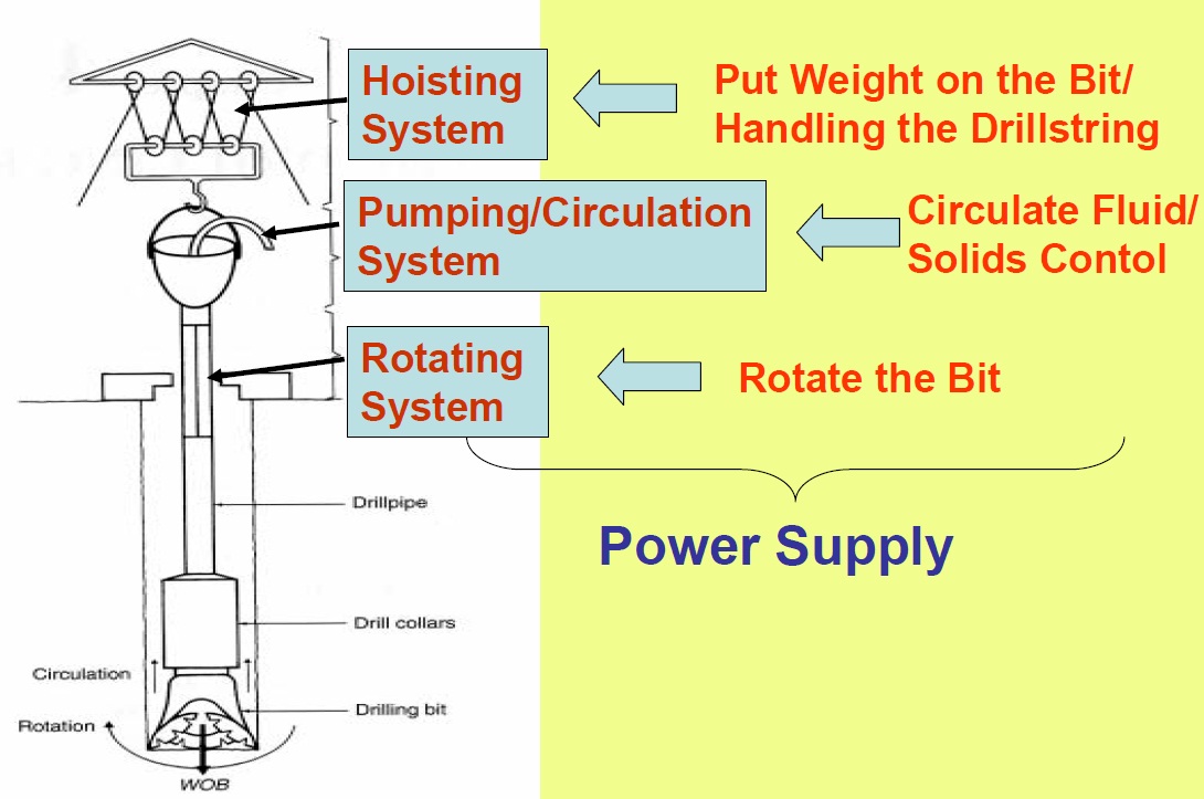 Fig. 2.1: Principles of the Hoisting Function
2.2 HOISTING EQUIPMENT
The equipment includes:
- the hoisting tower structure,
- the draw works and its accessories,
- the drilling line,
- the control panel.
2.2.1 The hoisting tower structure
This type is the oldest and derives directly from the tower that used to be built of wood. It is in the shape of a sharply pointed pyramid with one „foot“ in each corner resting on the angles of a square. The square is the rig floor (Fig. 2.2).
An upper platform, the water table, is what holds the drilling line sheaves, or crown block. Another platform between the two (about 85 ft high) is where the derrickman stands to rack up the lengths of drillpipe or drill collars.
The metal structure of the derrick can be welded or bolted together. There are practically no more derricks for onshore drilling because dismantling and reassembling operations are long, dangerous and therefore no longer economically viable at all.
In contrast, mobile rigs offshore use this construction technique because it is economical and well suited to offshore conditions. Here no dismantling is needed to move from one site to another, since it is the whole rig that is moved.
A distinctions is made between dynamic dericks and standard ones. The dynamic type is installed on floating supports such as ships and semisubmersibles. These derricks are subjected to extra dynamic stresses due to rolling, pitching and heaving of the support and to winds. The space available between the rig floor and the crown block must be higher to handle the wave-induced vertical movements of the floating support.
The specifications of two types of Dreco derrick are given below as an illustration.
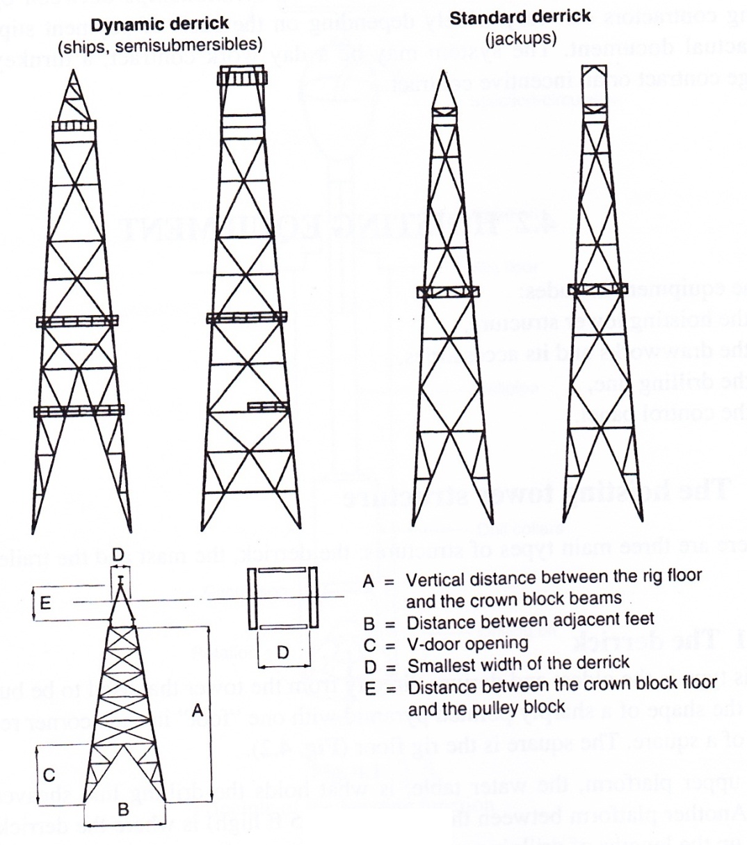 Fig. 2.2: Examples of Derricks
-
Dynamic derricks
Height ............................................... 160 ft (useful hook stroke length)
Base .................................................. 40 ft
Crown block platform ...................... 18 ft
V-door .............................................. 60 ft
Maximum hook load ........................ 1 000 000 lb
-
With 60 % of the drill string racked up, conditions of use are:
800000 lb hook load,
50 knots wind speed,
10 degrees of roll, with a period of 10 s,
3 degrees of pitch, with a period of 7 s,
5 ft of heave, with a period of 8 s,
4 x 24 t tensioners,
Traveling block at maximum height.
-
Waiting on weather with maximum drill string racked up:
250000 lb hook load (traveling block tied down to the rig floor),
70 konts wind speed,
15 degrees of roll, with a period of 10 s,
4 degrees of pitch, with a period of 7 s,
6 ft of heave, with a period of 8 s,
4 x 24 t tensioners,
Traveling block at maximum height.
-
Under extremely severe conditions:
250000 lb hook load,
100 knots wind speed,
30 degrees of roll, with a period of 10 s,
6 degrees of pitch, with a period of 7 s,
7 ft of heave, with a period of 8 s.
-
With 60 % of the drill string racked up, conditions of use are:
-
Standard derricks (jackups)
Height ............................................... 147 ft
Base .................................................. 30 ft
Top ......................................... 8 ft
V- door .............................................. 34 ft
-
Drilling
1000000 lb static hook load,
No racking,
85 mph wind speed.
-
Extremely severe conditions
115 mph wind speed,
No racking.
-
Running in casing
700000 lb hook load,
85 mph wind speed,
Maximum racking.
-
During towage
250000 lb hook load,
20 degrees of roll, with a period of 10 s.
-
Drilling
The main specification differences involve the free height available (an extra 13 ft to allow for the heave compensator) and the different hook loads according to specific conditions.
2.2.1.2 The mast (Figs. 2.3a and b, video 1)
The mast is a structure shaped like a very pointed A. It has the particular feature of being rotary jointed at the base so that it can be assembled or dismantled horizontally and then pulled to an upright position using the draw works and a special hoisting cable. This type of drilling tower is well suited to onshore drilling rigs requiring good deal of mobility. The racking board is in a cantilever position and lengths of pipe are racked on a floor, called the setback that is separate from the mast structure.
Technical specifications are identical to those for derricks:
- maximum hook load given the reeving system,
- free height available in the mast,
- width at the base,
- resistance to wind with and without racked drill string.
Capacities are comparable to those for derricks.
There are other less common types of masts that meet installation requirements on an offshore development platform where a conventional mast can not be placed in a horizontal position due to lack of room. The solution is to use a folding mast or a telescoping mast. The telescoping mast has two sections that fit together and are dismantled and laid down horizontally, taking up only half as much room.
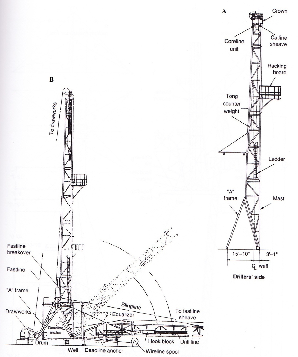 Fig. 2.3: a) Drilling Rig Mast; b) Schematic Diagram Showing How a Mast is Erected
2.2.1.3 The guyed trailerized mast
This type of mast is used with lightweight rigs and workover rigs (for production wells). It telescopes in two or three sections and the working position is at a forward slant. This requires a specific guying system for each rig.
Mast specifications
The drilling contractor must check to see that all cables and fittings are in a good state of repair and that anchor points are up to standards. The nominal capacity of this type of hoisting mast is based on precise tension values for guy wires. Most of these truck-mounted rigs have racking capacity only for doubles. It is exceptional to exceed a depth of 3000 m because there is not enough free height available under the substructure to accommodate the BOP stack required for this depth.
| Model | Hook load (lbs) | Board capacity | A | B | C | D | E | |||
| 4½" DP |
3½" DP |
2⅞" ODtubing |
⅞" rods |
(feet-inches) | ||||||
| 65´single pole |
105,500 4 lines |
67-0 | 38-8 | |||||||
| 120-69 | 100,000 4 lines |
2,500´ | 7,200´ singles |
7,200´ doubles |
69-0 |
25-4 29-4 |
53-10 55-9 57-8 |
41-0 | 4-4 | |
| 149-69 | 140,000 6 lines |
2,500´ 3,600´ |
7,200´ 10,200´ singles |
7,700´ 9,900´ doubles |
69-0 |
25-4 29-4 |
53-10 55-9 57-8 59-7 |
41-4 | 4-4 | |
| 140-91 | 140,000 6 lines |
3,850´ | 8,400´ doubles |
9,450´ triples |
91-0 | 54-3 55-0 55-9 |
77-0 78-0 79-0 |
55-5 | 4-4 | |
| 180-96 | 180,000 6 lines | 4,800´ | 12,480´ doubles | 11,550´ triples | 96-0 | 54-5 59-2 63-11 |
78-2 82-11 87-8 |
57-0 | 4-4 | |
| 215-96 | 215,000 6 lines |
7,200´ | 16,200´ doubles |
11,550´ triples |
96-0 | 54-8 59-11 65-2 |
78-0 82-9 87-6 |
58-0 | 4-4 | |
| 250-103 | 250,000 8 lines | 7,200´ | 16,200´ doubles | 11,550´ triples | 103-0 | 54-0 58-0 63-6 68-6 |
79-4 84-1 88-10 |
60-6 | 4-4 | |
| 250-108 | 250,000 8 lines | 7,200´ | 16,200´ doubles | 11,550´ triples | 108-0 | 58-0 63-6 68-6 |
79-4 84-1 88-10 |
65-6 | 4-4 | |
| 255-108 | 270,000 8 lines | 8,000´ doubles | 10,000´ doubles | 20,000´ doubles | 108-0 | 61-9 66-0 71-0 | 66-9 | 5-0 | ||
| 300-112 | 300,000 8 lines | 10,000´ doubles | 12,000´ doubles | 24,000´ doubles | 112-0 | 64-0 69-0 74-0 |
68-8 | 5-0 | ||
| 375-118 | 375,000 10 lines | 12,000´ doubles | 14,000´ doubles | 25,000´ doubles | 118-0 | 64-0 69-0 74-0 | 71-8 | 5-0 | ||
| 450-118 | 450,000 10 lines | 14,000´ doubles | 17,000´ doubles | 30,000´ doubles | 118-0 | 64-0 69-0 74-0 |
74-0 | 5-0 | ||
2.2.1.4 Substructures
These structures serve to raise the rig floor to leave room for wellhead assemblies and BOP stacks. They can be separate from the hoisting mast. Here they consist of box-like structures piled up on either side of the wellhead. The rig floor is assembled on top of the boxes and the hoisting mast sits directly on the box substructure. Most intermediate-capacity masts are an integral part of a hoisting assembly with an elevating substructure where the draw works and racking floors are folded at ground level by girders articulated in the shape of a parallelogram. Once the mast has been erected by the draw works, the floor is pulled into an unfolded position using the drilling line (Fig. 2.5).
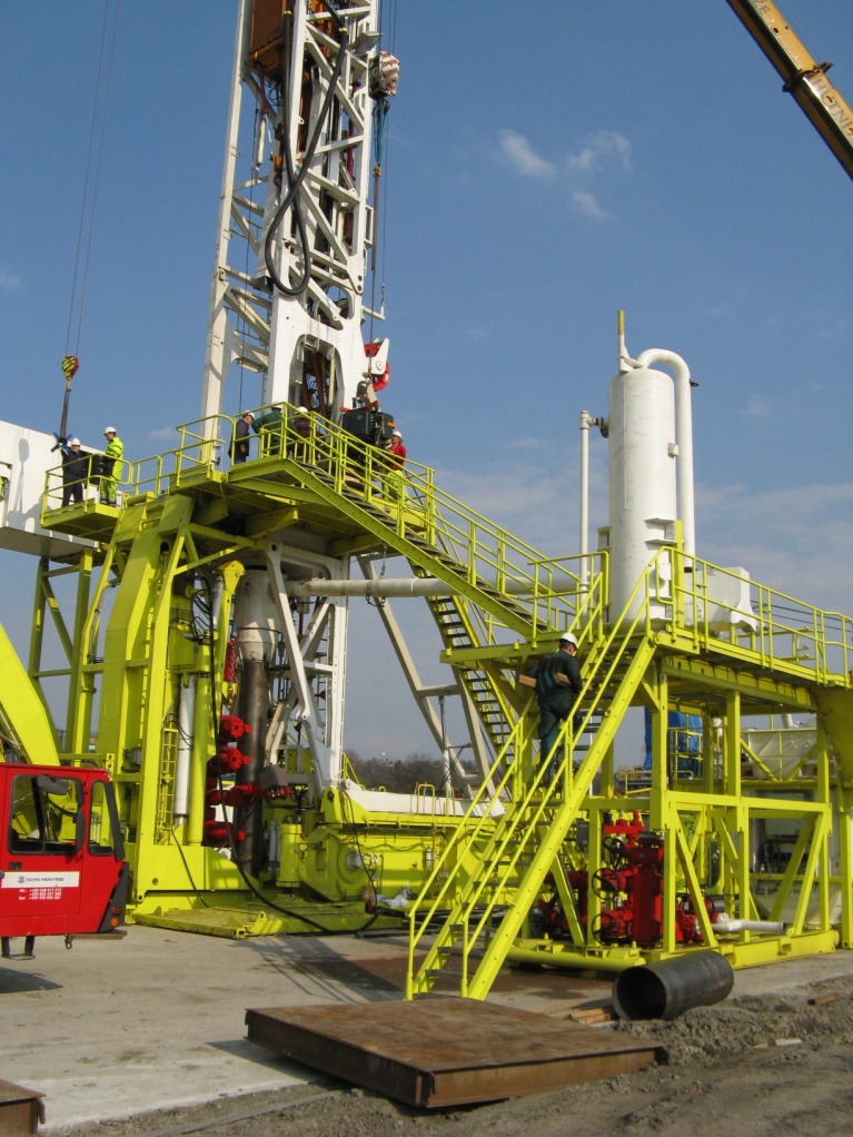 Fig. 2.5: Folding Substructure (Source: Huisman comp.)
2.2.2 Hoisting mechanics
2.2.2.1 The drilling line reeving system
Figure 2.6 gives a schematic idea of how the drilling line is strung up and of the component parts of the system.
A. Deadline
The drilling line is secured to a specific deadline anchor (Fig. 2.7) which measures the tension on that end of the line. It also allows new lengths of line to be run into the system in order to relieve the worn parts of the line by moving them from critical wear points on the pulleys of the crown block or the traveling block. Slipping the line, then cutting it off helps lengthen the lifetime of the drilling line.
B. Crown block
The crown block is the set of pulleys that the drilling line passes through. It is supported by the top platform of the drilling mast or derrick. The load on the crown block, and in turn on the mast or derrick, is greater than the load on the hook. The reeving system is such that there are two more lines on the crown block, the deadline and the fastline which is connected to the draw works drum. If the reeving system has ten lines and the load on the hook is 150 t for example, the line is under 15 t of tension in static conditions. But the hook is 150 t for example; the line is under 15 t of tension in static conditions. But the crown block supports 150 t + 2 x 15 t, i.e. 180 t.
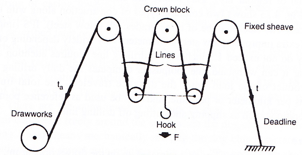 Fig. 2.6: Reving the Drilling Line (Source: Drilling Data Handbook, Editions Technip, Paris, 1989)
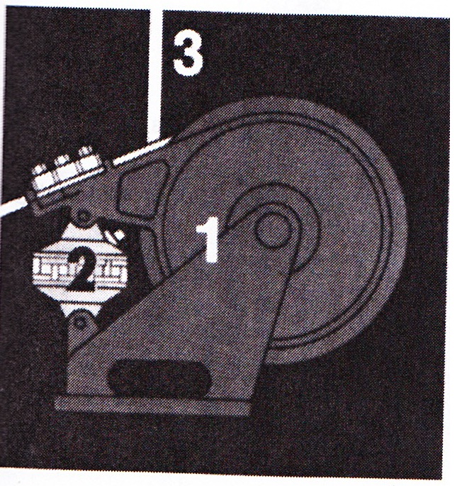 Fig. 2.7: Deadline Tie Down (Source: Totco) 1. Deadline anchor. 2. Hydraulic tension measurement cell. 3. Drilling line.
C. The traveling block and hook
The two are usually manufactured in a solid block, i.e. the pulleys, or sheaves and the hook are assembled in a compact package. The hook has a shock absorber to lessen stresses when the load is picked up and make screwing connections easier. The elevator bails are connected to two side hooks.
D. The drilling line
Drilling line has a metal core with six steel wire strands braided, or cabled around it. The lay of the wires made into strands is the opposite of the lay of the strands on the core of the wire rope (normal or regular lay). This makes the drilling line stiffer but somewhat less prone to rotate. The steel may be of three grades: PS (plow steel), IPS (improved plow steel) and EIPS (extra improved plow steel). Diameters vary widely depending on the type of rig, but generally do not exceed 1.5 inches. The drilling line requires attention and care. To evaluate the wear it can withstand, the toolpusher computes the daily drilling line service which is the product of the load times the distance traveled. The total line service is expressed in tons per kilometer or per mile, and will be used as reference points to initiate maintenance operations such as slipping and cutting of drilling line.
E. The fastline
This is the end of the drilling line that is reeled up on the draw works drum.
2.2.2.2 The Draw works
The draw works is the heart of the drilling rig. As mentioned earlier, it is the capacity of the draw works that characterizes a rig and indicates the depth rating for the boreholes that can be drilled.
The different mechanical parts are:
- A grooved drum where the drilling line will be reeled up (Fig. 2.8). There are brake rims on the edges of the drum where the brake bands are mounted. The brake controls the lowering speed of the load hanging from the hook. The system is highly reliable but does not have enough capacity to absorb all the energy produced by a string of casing lowered to great depths. All draw works are equipped with an auxiliary device, which is mounted on the drum shaft, to slow down the load. This will be described later on.
- A gearbox behind the draw works enables the driller to select from two or three gear ratios. Two ratios are sufficient when the draw works is electrically driven. Here regulating the variation in rotation speed is well controlled. Two parallel shafts are connected by pairs of sprockets and chains. There is the same number of pairs as gear ratios. One of the sprockets in each pair can rotate freely around the shaft when the dog clutch system is disengaged. Engaging a gear means mechanically moving the dog clutch system so that it blocks the rotation of the sprocket in relation to its shaft. The secondary shaft then rotates at the speed corresponding to the selected reduction ratio. The secondary shaft also causes the draw works drum to rotate by means of two pairs of sprockets and chains located on either side of the gearbox housing. These two extra ratios (low and high drum drives) are engaged by Airflex-type air clutches. A schematic diagram of the complete power transmission layout for a medium power range draw works.
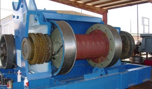 Fig. 2.8: Draw Works Drum
2.2.2.3 Auxiliary brakes
The braking capacity of the band system is not dynamically adequate when heavier loads are lowered into the well. This is why there is an added slowdown brake incorporated in the draw works drum axis on all rigs. Two types of mechanisms are used:
- The hydrodynamic brake. The operating principle is to convert the mechanical energy produced by lowering a load into heat by means of a rotor that is made to rotate by the draw works drum. The amount of mechanical energy that can be absorbed depends on the rotation speed and on the volume of water circulating in the working chamber. In order to adapt the deceleration to the load, the driller regulates the level of water in a small tall surge tank located in the water cooling circuit. The tank adjusts the amount of fluid in the brake and varies the braking torque (Fig. 2.9).
The system is reliable and requires very little maintenance, but it has major drawbacks: it provides little braking at slow speeds and regulation is too inflexible. As a result, its use is confined to lightweight drilling rigs.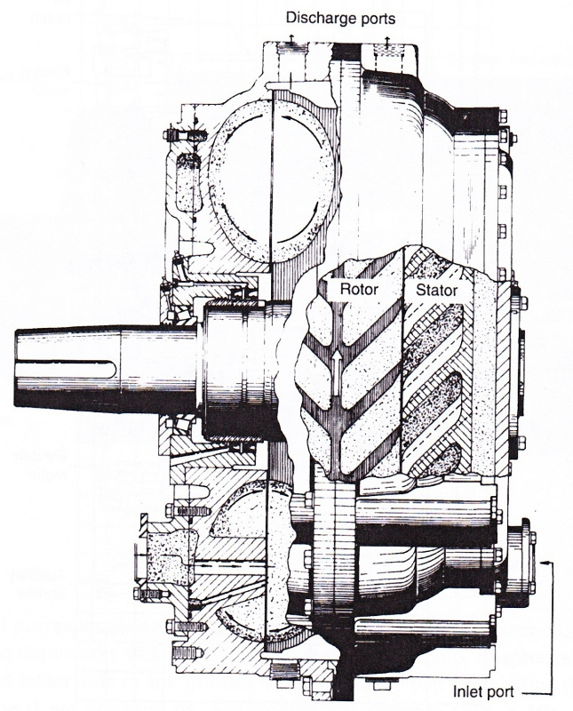 Fig. 2.9: Hydrodynamic brake (Parkersbourg type) (Source: PARMAC)
- The eddy-current brake which includes a driven element (rotor) and a stationary member which provides a controllable and adjustable magnetic field. The rotor cuts the lines of the magnetic field. The electromagnetic forces induced in the rotor tend to oppose the rotary movement. The eddy currents produced in the rotor generate heat by Joule effect. The heat is dissipated by a water circulation system. The amount of braking torque is related to the intensity of the magnetic field produced by soils and as a result this type of brake very flexible to operate.
2.2.2.4 Rig floor tools and equipment (video 4)
There are two types of tools and equipment: the ones used for hoisting and the ones used for screwing, making up and breaking out the drill string.
- Hoisting tools: The drilling hook has an ear-shaped device on either side for the bails that support an elevator. For each nominal dimension of pipe there is a type of elevator. It is common to use lifting subs that are screwed to the drill collar thread in order to hoist drill collars. The upper part of the sub has the same dimensions as drillpipe so that elevators do not have to be switched.
To hang the drill string on the rotary table, slips are placed in the master bushing (Fig. 2.10). For safer handling of slick drill collars, i.e. drill collars without any recess, a clamp is used on top of the slips. To make the crew´s work easier on the rig floor, some pipe slips are pneumatically powered and can be operated directly by the driller (Fig. 2.11).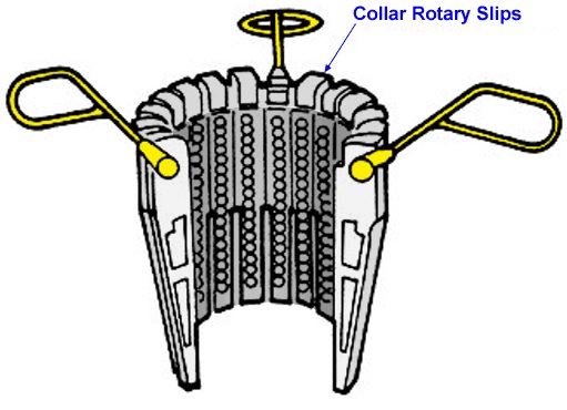 Fig. 2.10: Examples of Slips, Safety Clamp and Master Bushing
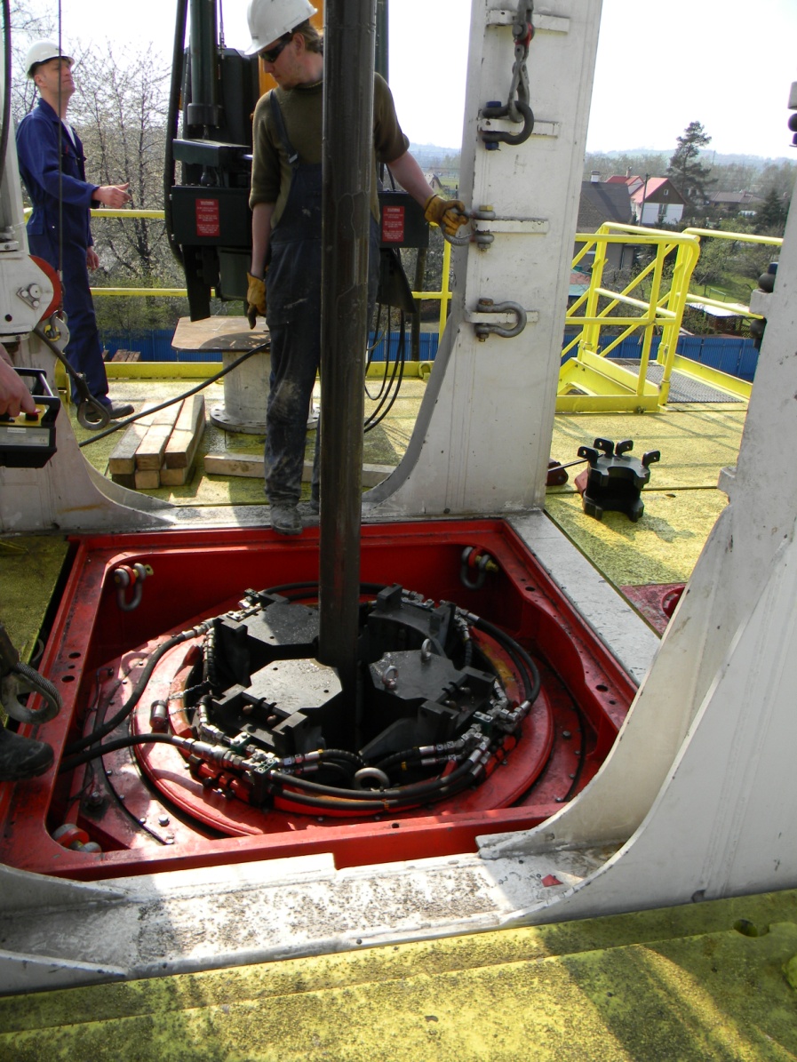 Fig. 2.11: Pneumatic Power Slips
- Screwing tools: Makeup and breakout torque is still very commonly applied with multiple-jaw tongs. The backup tong is secured to a stationary point by line or chain. The other is connected to a head that is rotated by the cathead transmission. The pulling force exerted by the cathead provides torque on the tubular by means of the lever arm corresponding to the length of the tong. Two crew men are required to pace and remove these tongs.
The first phase in screwing pipe together, i.e. putting the two ends together until the box and pin shoulders meet, should be performed as quickly as possible. For quick connections, a chain wrapped around the pipe is still very commonly used. One end of the chain is held tight by a crew man. The other end rolls up on the spinning cathead controlled by the driller. The winch effect rotates the pipe as the chain spins.
The spinning chain method is quick but requires a lot of skill and good coordination. It is hazardous for the crew man who is in charge of pulling and holding the laps of chain around the pipe. Safety would dictate using only pneumatic power tongs.
Any and all offshore rigs, whatever the type, along with heavyweight onshore rigs are equipped with hydraulic robot tongs (Fig. 2.12) that can also operate on the mousehole. They are rail mounted so they can be rolled off to leave the rotary table clear when necessary.
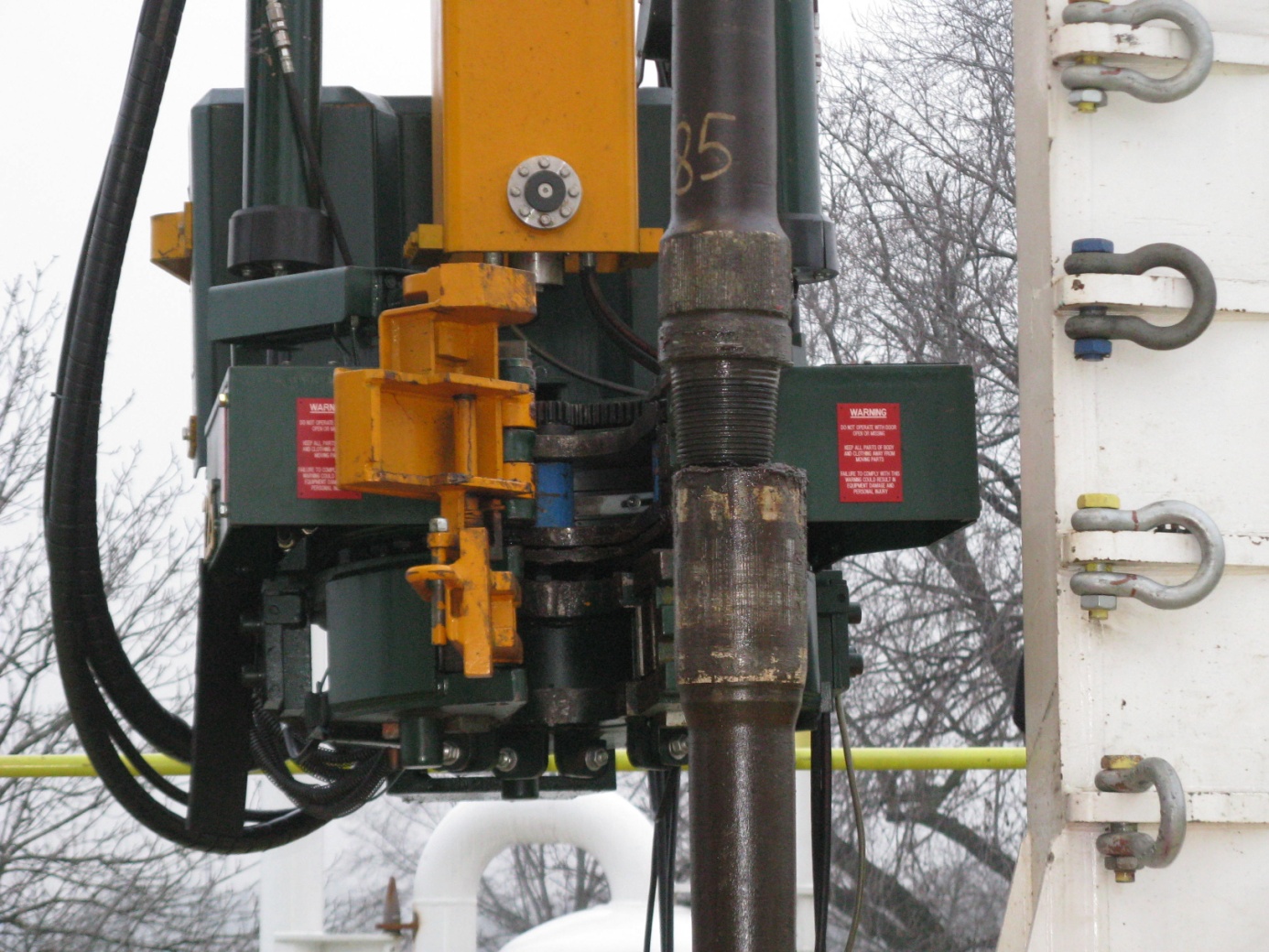 Fig. 2.12: Robot Tongs to Assemble and Make Up Pipe
2.3 ROTATING EQUIPMENT
2.3.1 The rotary table (Fig. 2.13)
This mechanical apparatus is very simple and requires only little maintenance, and this is what makes it so attractive for the working conditions on a rig. The main bearing supports the maximum load in static conditions or at slow rotation speed. During drilling (above 50 rpm) in fact, the weight of the drill string is hanging from the hook. Rotary table maintenance consists in checking the level and quality of the oil in the lubrication system. The nominal size is characterized by the through diameter where the master bushing is installed. The master bushing serves to hold the drill string by means of the slips and to drive the kelly drive bushing during drilling. Nominal sizes in inches may be as follows: 17½, 20½, 27½, 37½ and 49½.
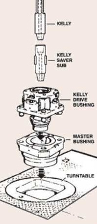 Fig. 2.13: Rotary Table Terminology
The rotary table is driven by means of a sprocket and chain by the draw works (the gear ratios of the gearbox can then be used). It can also be driven by means of an electric motor independent of the draw works transmission on heavyweight rigs.
2.3.2 The kelly
The components connected to the kelly will be discussed from a more general standpoint (Fig. 2.14).
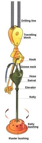 Fig. 2.14: Kelly Terminology
2.3.2.1 The kelly
The kelly can have a square, hexagonal or triangular cross-section. It is rotated by the table and by means of the kelly drive bushing that it fits into. The kelly bushing is equipped with four horizontal axis rollers so designed as to transmit torque to the kelly and in turn to the drill string screwed onto the lower kelly coupling. The whole assembly can slide freely up and down along the kelly´s stroke length. With a total length of 40 ft or 54 ft, the kelly has a useful stroke length of 37 ft or 51 ft respectively.
To control any incipient blowouts that might occur through the inside of the drill string, safety valves are mounted on each end of the kelly (lower kelly valve and upper kelly cock). The two valves are operated by rotating ninety degrees with a wrench that is kept on the rig floor. The lower valve must have a small enough diameter so that it can be run into the borehole that is being drilled.
2.3.2.2 The kelly saver sub
Each time a length of drillpipe is added, i.e. after the useful length of the kelly has been drilled, the kelly must be unscrewed from the drill string, then screwed back onto it. Since this is done often, the drill string is screwed and unscrewed from a low-cost coupling rather than from the threads on the bottom of the kelly itself. Because the sub rotates inside the BOPs, a rubber protector is placed on the outside sub diameter to protect them from wear.
2.3.2.3 The swivel
This component hangs from the lifting hook by its bail. It is designed for both the maximum drill string load and for the maximum rotational speed. Additionally, a rotating seal allows drilling fluid to be injected under pressure by the mud hose connected to the swivel gooseneck.
It should be noted that all connections above the useful section of the kelly have a left-handed thread so that they are not broken out by the rotary table turning to the right.
2.3.3 The power swivel
As the name indicates, this is a swivel that fulfills the same functions as conventional ones but also provides mechanical transmission to the rotary string. It may be driven in the same way as independent rotary tables, i.e. by direct-current electric motor or by hydraulic motor. The hydraulic option is less conventional in design and requires installation of a unit with specific hydraulic power.
Though the advantages of the power swivel as described later on are very attractive, installing one entails a number of constraints:
- a dolly, or trolley beam guide system, must be installed in the derrick to absorb reactive torque,
- the structure must be reinforced because of the extra torsion stress,
- the derrick must be built up since the power swivel is longer than a conventional one,
- extra hoses and electric cables need to be on hand on the rig,
- the weight above ground increases considerably,
- extra investment is required and maintenance in particular is a much heavier job than with a rotary table and kelly system.
However, the advantages of the system dictate using a power swivel when costly development operations are involved, such as in the North Sea:
- no need to handle a kelly,
- can be reconnected to the drill string at any mast height during tripping,
- drilling with thribbles is possible,
- the drill string can be pulled out while rotating and circulating: back reaming,
- extra-long core sample can be taken,
- no need to unrack the drill string between two development wells when the rig can be moved with the mast erect and drill string racked up on the rig,
- static torque can be applied for a much longer time (only when the swivel is hydraulically driven).
Figure 2.15 illustrates all the ancillary components of the power swivel. The degree of complexity is a good indication of the maintenance requirements.
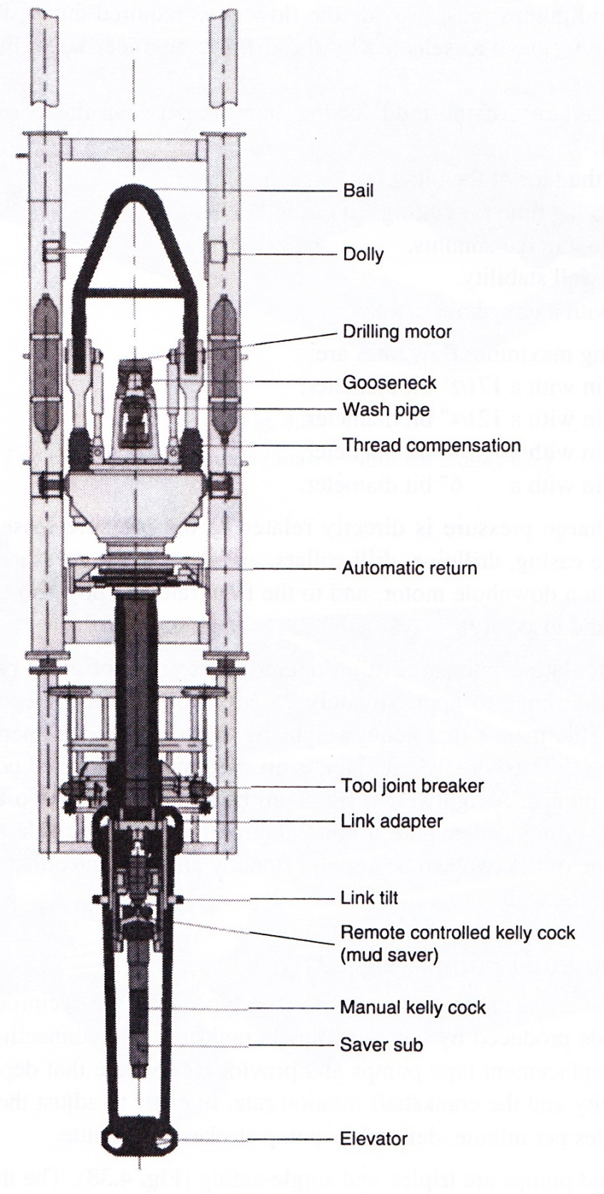 Fig. 2.15: Power swivel assembly (Source: ACB)
2.3.4 Pumping equipment
2.3.4.1 Conventional requirements
Drilling fluid pumps must provide the flow rates required during the different drilling phases. The flow rates are selected by the drilling engineer according to the following criteria:
- annular velocity of the mud (in the annulus between the borehole walls and the drillpipe),
- cleaning the face of the bit,
- maximum lag time for cuttings to reach the surface,
- type of flow in the annulus,
- borehole wall stability,
- drilling with a downhole motor.
The resulting maximum flow rates are:
3500 l/min with a 17½" bit diameter,
2500 l/min with a 12¼" bit diameter,
1500 l/min with a 8½" bit diameter,
600 l/min with a 6" bit diameter.
Pump discharge pressure is directly related to the pressure losses in the circulating system (surface casing, drillpipe, drill collars, annulus), to the pressure drop in the drilling bit nozzles or in a downhole motor, and to the flow rate and physical characteristics of the fluid (density and viscosity).
Modern circulating pumps have an operating pressure of 5000 psi, i.e. 35 MPa, but users restrict the range to approximately 25 MPa for reasons of operational safety and maintenance. This means that heavyweight rigs need to be equipped with two 1600 hp pumps (1200 kW). Offshore, where there is no skimping on installed power, there are often three 1600 HP pumps. A lightweight rig could be equipped with two 800 hp pumps. Two independent pumping systems are a must, though they must be able to work at the same time, so that one of the two can be kept on standby and guarantee that the mud can always be circulated in the well.
2.3.4.2 Circulating pumps (Fig. 2.16, video 9)
Mud pumps are of the reciprocating piston-type, with the reciprocating movement of pistons and rods produced by a conventional crankshaft and connecting rod system. They are positive-displacement type pumps and provide a flow rate that depends directly on the cylinder capacity and the crankshaft rotation rate. In order to adjust the flow rate, the crew counts the cycles per minute, defined by pump strokes per minute.
Modern mud pumps are triplex and single-acting (Fig. 2.17). The three pistons move in dismountable cylinder liners, suck up the fluid by a suction pipe, then discharge it into a discharge pipe through a discharge valve.
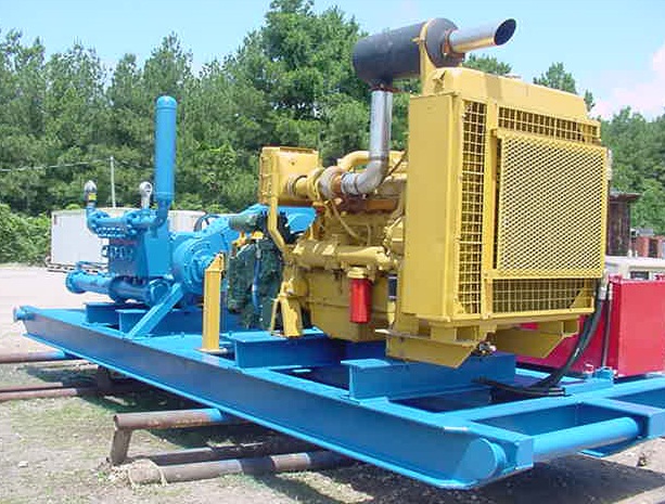 Fig. 2.16: Triplex Drilling Mud Pump
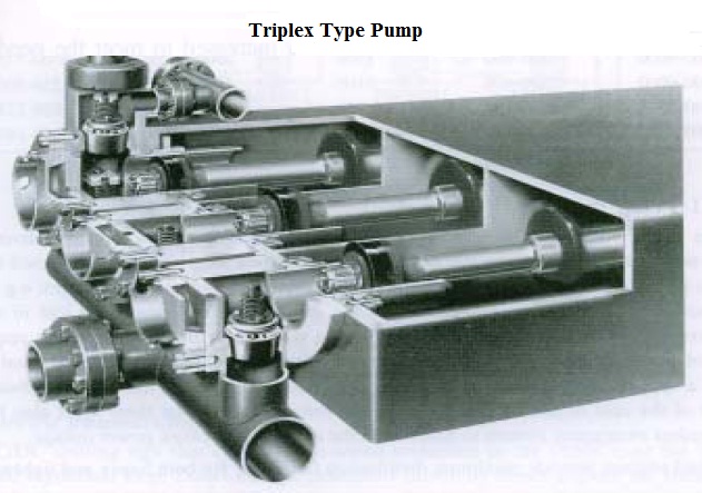 Fig. 2.17: Cutaway View of a Triplex Pump (Source: Mission Drilling Products)
An important feature of this type of pump is that the cylinder capacity can be altered by changing the diameter of the cylinder liner. When a maximum flow rate is required, the pump is equipped with the largest size liner. When maximum pressure is required (5000 psi – 35 MPa), a liner with a smaller cross-section is usually necessary.
This type of pump can not usually suck up fluid directly from the mud pits because of volumetric efficiency and cavitation risks due to high linear piston velocities. As a result, they are boosted, or supercharged, by a centrifugal pump.
2.3.5 Power and power transmission
The installed capacity on a drilling rig has constantly increased to meet the needs of modern drilling techniques. The table below gives a breakdown of power ranges.
| depth reached (m) |
hook load (t) |
draw works rating (kW) |
pump rating (kW) |
total installed capacity (kW) |
|---|---|---|---|---|
| 6000-9000 4000-6000 3000-4000 900-3000 | 400-600 300-400 200-300 100-170 | 1500 1100 750 300-525 | 2000-2600 1800-2000 1100-1800 750-1100 | 3000-3750 2250-3000 1850-2250 1100-1850 |
2.3.5.1 Prime movers
The steam engine was replaced by the diesel engine long ago as a prime mover, but production platforms often use gas turbines. Some drilling sites are even connected to the electric power distribution network. Although electricity offers major advantages, e.g. low-cost, noiseless energy, the self-reliance of the drilling site is jeopardized and in many instances this is unacceptable. Additionally, the way the drilling site operates requires peaks of power which are not admissible on the distribution network. This technical snag means a specific infrastructure must be incorporated in the site. It has quite a substantial impact of the cost of the rig and furthermore, safety dictates that there must also be an independent emergency system to function in the event of a network power outage.
Diesel engines provide maximum distribution flexibility for both heavy and lightweight rigs.
2.3.5.2 Power transmission systems
The three basic systems are mechanical, hydraulic and electric.
A. Mechanical transmission
Several diesel engines are parallel-operated through interconnection by a chain and clutch system called a compound. They are fitted with torque converters. The driller assigns the engines to rig components depending on his needs: during drilling, one or two engines for pumping, one for the rotary table transmission; during tripping all the engines can be assigned to the draw works.
This type of transmission allows easy maintenance and use, but it does lack flexibility in utilization and location. It is now used only for lightweight, truck-mounted rigs. Here the size of all components (engine, transmission) is such that everything is kept on board and requires no complex mechanical dismantling and reassembly at the end of each drilling operation. In this type of setup, each mud pump has its own separate diesel engine.
B. Electric transmission
DC/DC drilling rigs that came on the scene sometime in the 1950s used the Ward-Leonard regulation loop. Direct-current generators driven by diesel engines are connected in a loop with the direct-current draw works and pump motors. The system was conventional at the time, but had a number of drawbacks, e.g. lack of flexibility in utilization and the need to have one diesel engine for each generator. On the other hand, it was not very complex, fairly simple to use and cheap.
The advent of SCR or silicon controlled rectifiers made it possible to develop the AC/DC system. Here electric power is produced by means of a three-phase alternator. Direct-current motors are then powered by SCR rectified current.
C. Hydrostatic transmission
Other than a few prototype exceptions, this type of transmission is found only on lightweight slim-hole rigs or used to power independent components, e.g. power swivel, rotary table.
The mechanical energy supplied by diesel engines is converted into a pressurized oil flow. The hydraulic energy is conveyed by high-pressure hose to hydraulic motors on the draw works, rotary table, swivel or pumps.
2.3.6 The control panel (video 2)
All measurement indicators are grouped together on a pressurized explosion-proof panel (Fig. 2.18).
The weight indicator showing the load on the hook is the most important instrument, or in any case the one most often checked by the driller. One of the two needles gives the weight hanging from the hook and the other gives the difference between the drill string off bottom and on bottom, i.e. the weight on the bit (WOB).
Fig. 2.18: Control panel of a modern heavyweight rig
The other indicators tell the crew the level in the mud pits; mud circulation data, e.g. flow rate, pressure and pump strokes; rotation parameters, e.g. rotary table engine torque and rotational speed; and make up torque measurements on tubulars.
Most of these parameters are recorded in the mud logging office when there is one. In any case the drilling contractor is under contractual obligation to hand over a copy of the drilling parameter recordings to the operator along with the daily drilling report.
Drilling parameter recorder shows a continuous band recorder for six parameters:
- hook load,
- rate of penetration,
- rotational speed,
- rotary table torque,
- pump strokes per minute,
- pump discharge pressure.
The three measurements that are indispensable to operations are hook load, rotary table rpm and pump discharge pressure.
3 DRILLIN FLUIDS
The technical breakthrough that resulted from using a fluid in continuous circulation in a borehole was discussed in the introduction. The fluid, as a drilling parameter, has a host of operational features and accordingly fulfills some very important functions. Drilling performance records have made considerable headway due to technical progress in the physicochemical nature of drilling fluids. This is why this chapter on drilling fluids will focus first and foremost on the fluid´s functions before dealing with the different types of fluid and how each one is used on a well site.
3.1 FUNCTIONS AND CHARACTERISTICS OF DRILLING FLUIDS
3.1.1 Transporting cuttings to the surface
The fluid circulating and rising in the drillpipe/borehole wall annulus must sweep the cuttings from the working face up to the surface. Three parameters influence the effectiveness of the annular cleaning function.
3.1.1.1 Annular velocity of the fluid
The velocity depends on the fluid flow rate and the annular cross-sectional area:
V (in m/min) = velocity of the mud,
Q (in 1/min) = pumping rate,
Va (in 1/m) = unit volume of the annulus.
The usual range for annular velocity is from 25 to 60 m/min.
3.1.1.2 Density
It is because of the Archimedean principle, i.e. the buoyancy of the cuttings, that the density parameter influences how readily the cuttings are moved up the annulus. However, the density parameter is not altered in order to improve on this function.
3.1.1.3 Viscosity
The cuttings velocity can be considered as the difference between the rising velocity of the drilling fluid in the annulus and the settling velocity of the cuttings. The settling velocity depends on the size, shape and mass of the particles; on the rheology of the fluid and more particularly on its viscosity. A minimum viscosity value is needed to get the best match between the mud velocity and the cuttings velocity.
3.1.2 Suspending the cuttings when circulation is stopped
Drilling fluid circulation must be stopped when a length of drillpipe is to be added. During shutdown, the cuttings rising in the annulus are no longer carried upwards and can suspended by gelling when the mud is no longer moving. Practically all viscous fluids are thixotropic.
3.1.3 Cooling the bit and lessening drill string friction
The drilling bit heats up because of the temperature downhole (geothermal gradient) and due to mechanical friction converted into calories. Circulating drilling fluid serves as a coolant, with the mud pits on the surface as heat exchanger. Additionally, the drilling fluid decreases the friction coefficient between the drill string and the wall of the hole. This function is sometimes enhanced by adding antifriction products such as oil or special additives.
3.1.4 Consolidating the walls of the hole
The liquid phase of the drilling mud filters into permeable formations and deposits a film of colloidal particles on the walls of the hole. The film is termed cake and it is reinforced by specific products called filtrate reducers. This is what plasters and isolates the permeable formations in the borehole, allowing longer stretches of uncased hole by helping to stabilize the formations.
3.1.5 Preventing inflows of formation fluids into the well
The drilling fluid exerts a hydrostatic pressure of Ph = 9,81 Zd (in kPa). If the pressure Ph remains higher than the pressure of formation fluids, no fluids will enter the borehole. The drilling mud is considered as the first blowout preventer to control pressures downhole.
3.1.6 Acting as a drilling parameter
The choice of the type and properties of drilling mud govern the instantaneous rate of penetration by the mud´s capacity to sweep the bit area clean.
In addition, a downhole pressure produced by the drilling fluid and higher than formational pressure is always detrimental to drilling rate. (Use of air or foam as drilling fluids when possible).
3.1.7 Transmitting power to a downhole motor
In some applications such as directional drilling or diamond bit drilling, a downhole motor (turbine or positive-displacement motor) is incorporated in the drill string to rotate only the bit and nothing else. The motor is driven by the flow rate of the mud pumped down the drill string. The pressure drop due to the operation of the downhole motor is added to the pressure losses in the discharge circuit.
3.1.8 Providing geological information
Because it circulates, the drilling fluid conveys major items of information for the geologist. Some examples are the cuttings that the geologist takes out of the mud return line and the traces of fluids or gases from drilled formations that are detected by sensors on the surface. The physicochemical changes in the fluid (temperature, pH, chloride content, etc.) are also an integral part of mud logging measurements that tell the geologist and the driller how drilling is proceeding.
3.1.9 Conclusion
Following this brief discussion of the different functions of drilling fluid, the type of fluid flow will now be dealt with. To determine the type of flow, a mud rheogram will be plotted on the basis of mud measurements and will classify the fluid along the lines of recognized models.
The characteristics such as viscosity, yield point, N and K numbers and gel strength can be calculated. Another important physical property is of course density.
3.2 MUD MEASUREMENTS
3.2.1 Density (video 10)
3.2.1.1 Definition
This is the ratio of the weight of a substance, to its volume under specific pressure and temperature conditions. It is expressed in N/m3 or more practically in kg/l. Note that to convert from nonmetric units:
10 lb/gal = 74,8 lb/cu ft = 1,2 kg/l
3.2.1.2 Measurement apparatus
Density is measured with a mud balance (Fig. 3.1) based on the same principle as a beam balance. Density is very important and must be checked regularly as it must be high enough to control formation fluids. However, it must not be too high compared to the formation fracturing pressure. There are also continuous density measurement devices that are fitted on the discharge end of the drilling mud pumps. They work on the basis of measuring how the mud attenuates radiation by a radioactive source.
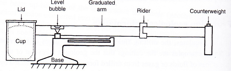 Fig. 3.1: Mud Balance
3.2.2 Viscosity (video 11)
3.2.2.1 Marsh viscosity (Fig. 3.2)
The principle is to measure the time it takes a given volume of fluid to drain out through the calibrated orifice of a funnel.
The funnel is filled with 1500 cm3 of homogeneous mud, then the time required for a quarter of a gallon (946 cm3) to drain out is measured. Marsh viscosity is therefore expressed in seconds. The viscosity of pure water at a temperature of 20 °C is 26 seconds (946 cm3).
Marsh viscosity is a practical indication since it can be done quickly on the mud pits, but is gives only a very relative assessment of the characteristics of the mud. It is mainly used to provide a rough but rapid evaluation of any contamination that might dramatically modify the fluid´s properties.
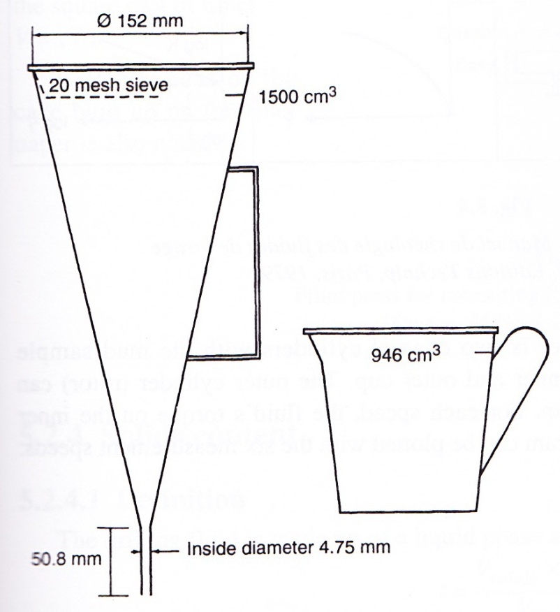 Fig. 3.2: Marsh Viscosity Meter
3.2.2.2 Fann viscosity (Fig. 3.3)
The Fann viscometer is a device that can help determine the drilling fluid rheogram, i.e. the flow law that is represented by the function:
where
γ = shear rate (Fig. 5.4)
The principle of the viscosity meter is two coaxial cylinders with the mud sample contained of the viscosity meter is two coaxial cylinders with the mud sample contained in the annulus between the inner and outer cup. The outer cylinder (rotor) can rotate at 3, 6, 100, 200, 300 or 600 rpm. For each speed, the fluid´s torque on the inner cylinder (stator) is measured. The rheogram can be plotted with the six measurement speeds.
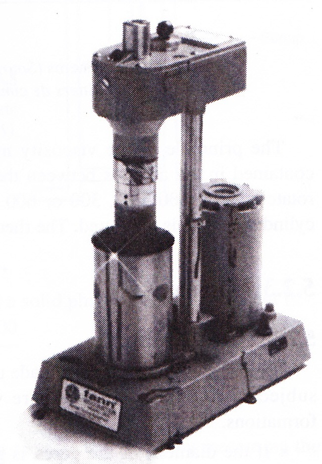 Fig. 3.3: Fann Viscosimeter
3.2.3 Filtrate
3.2.3.1 Description
The drilling fluid, which is made up of a liquid phase and suspended clayey products, is subjected to hydrostatic pressure while it is in contact with porous and permeable formations.
- If the diameter of the pores is greater than the diameter of the suspended clays, the formation will absorb the whole fluid. The extreme case is lost circulation where the fluid flow is entirely absorbed by the formation and there is no mud return to the surface.
- If the diameter of the pores is smaller than part of the suspended particles, there is filtration, i.e. the clay products will be laid down on the wall of the hole. A filter cake will be formed and the base liquid (filtrate) will invade the formation. The permeability of the cake conditions filtration.
3.2.4 Solids content
3.2.4.1 Definition
The drilling fluid is made up of a liquid phase and a solid phase. The solids content is:
3.2.4.2 Measurement
The two phases are separated by distillation. Then t can be calculated by measuring the volume of liquid collected:
3.3 DIFFERENT TYPES OF DRILLING MUD AND MAIN COMPONENTS
Drilling muds are commonly classified according to the base fluid, i.e.:
- water-base muds,
- oil-base muds.
Air, foam and aerated muds can also be used as drilling fluids.
First the main product used in making up drilling fluids will be listed, then the most commonly used muds and the areas where they are used will be described. The standard composition will be illustrated with examples in the form of tables.
It should be remembered that these are only standard examples. Whenever there is a problem of maintaining the properties of a fluid, it is necessary to make a specific study and often a more complex formulation and treatment.
3.3.1 The main mud products
3.3.1.1 Viscosifiers6
| name | secondary function | area of use |
|---|---|---|
| Clay for fresh water (bentonite) |
Effective filter bed | Fresh-water mud, Cl- content <25 g/l |
| Clay for salt water (attapulgite) |
Cl- content salt-water mud | |
| Bioplymer | Shear-rate thinning | Low-solids, low density mud |
3.3.1.2 Filtrate reducers
| name | secondary function | area of use |
|---|---|---|
| Starch | Viscosifier | Salt-saturated drilling mud, temperature <150 °C |
| Technical CMC Low viscosity High viscosity |
Slight viscosifier Strong viscosifier |
Ca++ content <500 g/l and Cl- content <30 g/l |
| Refined CMC Low viscosity High viscosity |
Slight viscosifier Strong viscosifier |
Ca++ content <500 g/l and Cl- content <30 g/l |
| Polyanionic polymer | Viscosifier, stabilizes shales | Seawater mud |
| Emulsified oil | Lubrication | Emulsified mud |
3.3.1.3 Dispersants
| name | secondary function | areas of use |
|---|---|---|
| Tannin | Fresh-water muds Ca++ content <300 g/l and Cl- content <20 g/l |
|
| FCL (iron or chrome lignosulfonate) | Filtrate reducer Inhibits swelling at higher concentration |
Salt- or fresh-water muds FCL muds pH >9 Temperature <200 °C |
| LC (lignochromates or lignites) | Reinforces FCL action High temperatures |
3.3.1.4 pH control
| NaOH (caustic) | Precipitates calcium Extender to increase clay yield |
3.3.1.5 Calcium precipitation
| Na2CO3 | Extender to increase clay yield |
3.3.1.6 Weighting materials
- Barite (BaSO4): average density 4,3.
- Hematite (Fe2O3): 4,9 <d<5,3.
- Siderite (FeCO3): 3,7 <d<3,9. Soluble in hydrochloric acid, so mainly used in completion fluids.
- Galena (PbS): 6,7 <d<7. Weighting material for special cases.
- Calcium carbonate (CaCO3): 2,6 <d<2,8. For low-density fluids that can be acidified.
3.3.1.7 Lost circulation materials
These materials are used to plug up permeable zones. There are several types:
- granular: hard, calibrated products made of walnut shells, apricot, cherry or olive stones, etc.,
- fibrous: designed to „weave“ the granular materials together, made of wood, sugar cane or cellulose fibers, etc.,
- flaky: to cover over the previously listed materials, cellophane waste, mica, etc.
3.3.2 Types of drilling fluids
3.3.2.1 Water-base muds
Straight bentonite mud
| average composition (/m3) |
characteristics | stability toward contaminants |
area of use |
|---|---|---|---|
| Bentonite: 40 to 60 kg CMC: 0 to 5 kg Caustic for pH: 8.5 to 9 |
Low initial density: 1.03 to 1.05 |
Slight | Soud mud Few contamination problems |
Bentonite mud with tanning extracts
| Bentonite: 40 to 60 kg Tannin: 2 to 4 kg Caustic: 0.5 to 1 kg CMC: 1 to 5 kg | pH<11 Filtrate: 2 to 4 cm3 | Average Ca++< 300 mg/l Cl- < 20 g/l | Dept <3000 m Low-contamination zones (gypsum, anhydrite, shales) |
FCL/LC bentonite
| Bentonite: 50 to 60 kg FCL: 20 to 4 kg Caustic: 2 to 4 kg CMC: 0.5 kg Possibly with LC: 10 to 20 kg | pH<9 Holds up well to 200 °C | Good Cl- from 50 to 70 g/l | Dept <5000 to 6000 m Wide area of use: concentrations adjusted according to contamination (gypsum, anhydrite, shales) |
Gypsum mud
| Bentonite: 50 to 70 kg FCL: 12 to 15 kg Caustic: 3 to 4 kg Gypsum: 10 to 20 kg CMC: 5 to 10 kg Possibly LC | pH<9 Holds up well to 200 °C | Good Cl- from 60 to 70 g/l | Gypsum or anhydrine sections Shaly sections Slightly salt-bearing sections |
Salt-saturated mud with inorganic thinners
| Salt: 300 kg Clay: 50 kg (specific for salt-water mud) Starch: 30 to 40 kg Lime: 0 to 10 kg | d > 1.20 Corrosive Holds up moderately to temperature, 130 to 140 °C | Good with gypsum and anhydrite sections Fair with shales | Salt-bearing sections Zones with slightly or moderately dispersing shales |
Salt-saturated mud with organic thinners
| Salt: 350 kg Clay: 50 kg Starch: 20 to 30 kg | d > 1.20 Corrosive | Salt-bearing sections Shaly zones |
Emulsion mud
| Water-base mud + 5 to 10 % oil |
Same as water-base mud plus:
|
Same as water-base mud |
Same as water-base mud plus:
|
Seawater mud
| Bentonite: 75 to 100 kg Clay: 30 to 80 kg (for salt-water mud) Caustic: 5 to 10 kg FCL: 15 to 25 kg LC: 5 to 10 kg CMC: 1 to 5 kg (refined) | d = 1.10 to 1.15 pH = 9.5 to 10.5 Holds up well to tepmerature, 200 °C |
Good | Offshore for:
|
Polymer mud
| Bioplymer: 4 kg Chromic chloride: 1.2 kg Caustic: 8 to 10 kg Bactericide: 0.3 kg Bentonite: 5 kg Possibly plus FCL and CMC |
Very low solids dontent Minimum density 1.03 Filtrate > 12 cm3 Can be used in seawater |
Avarage | When formation problems are few, used in order to improve penetration rate |
3.3.2.2 Oil-base muds
There are two main types: oil-base muds (a few percent water) and invert muds.
-
Oil-base muds
Characteristics
- Oil-base muds cause the least damage to pay zones.
- They have the properties required for good drilling conditions.
- The oil does not filter much into formations.
- Drilling and coring in pay zones.
- Workover and maintenance of producing wells.
- Drilling sections where a water-base fluid would cause problems (swelling shales, stuck pipe, etc.).
- Base oil: 95 to 98 % of the volume. Diesel oil to highly asphaltic crude can be used with the following most important properties:
- specific gravity,
- flash point,
- acid number,
- aniline point.
- Water: 2 to 5 %, content must be monitored. Allows general characteristics of oil-base mud to be adjusted. Is emulsified.
- Rheological agents: to control filtration and viscosity, the following products are added:
- blown asphalt,
- organophilic clay,
- flame black, etc.
- Emulsifiers and stabilizers,
- Dispersants,
- Weighting materials:
- CaCO3,
- BaSO4,
- Galena.
- Water neutralizing agents.
The advantages of this type of mud are:
- Characteristics are easy to control when no water or crude influxes occur.
- The muds are insensitive to common water-base mud contaminants (NaCl, CaSO4, cement, shales).
- They have excellent static filtration characteristics with temperature and pressure; the cake is very thin.
- Wells can be drilled with a density close to one.
- Drill string drag on the walls of the hole is reduced, thereby decreasing twisting moment and drill string wear.
- Oil-base muds lengthen roller bit lifetime.
- There is no risk of differential-pressure sticking.
- Gives cores where the value of the content and nature of interstitial water can be better assessed.
- Compared to water-base mud drilling, increased productivity index.
- Less damage to formations.
However, some drawbacks may be:
- Sensitivity to water and to some crudes.
- Weighting materials may tend to settle out.
- Oil-base muds are dirtier to handle.
- Possible fire hazard.
- Rubbers not specifically designed for oil and gas duty may deteriorate.
- The presence of oil is harder to spot in the cuttings.
- Some mud logging and wireline logging methods can not be applied.
- Cost price per m3 is higher than for water-base mud.
-
Invert muds
These muds are drilling or completion fluids with a continuous oil phase and a dispersed aqueous phase of at least 50 % of the volume.
CharacteristicsThey have the same characteristics as oil-base muds, except that they perform better where oil-base muds are at a disadvantage.
Area of useThe are used in the same areas as oil-base muds:
- Thick sections of salts or anhydrite.
- Problems with drilling under high-temperature conditions.
- Problems of deviation.
- Drilling under low atmospheric temperature conditions.
They have the same positive points as oil-base muds, in addition:
- They are less of a fire hazard.
- Less expensive per m3.
- Easier to treat on the surface.
This type of mud came into use more recently than oil-base mud and has taken over practically all of the range of applications.
3.3.3 Drilling with air, foam or aerated mud (video 12, video 13)
3.3.3.1 Drilling with air
Compressed air is pumped into the drill string instead of drilling mud and it fulfills all the functions required for drilling. Below are the basic differences between using mud and air as drilling fluids:
- annular velocity is 900 m/min,
- there is very little hydrostatic pressure on the bottom,
- rate of penetration is considerable since pressure is negative on the working face,
- drilled formations are not invaded by the drilling fluid,
- a rotary blowout preventer, or diverter, is required at the wellhead,
- but air can not be used as drilling fluid if there are water influxes in the well.
3.3.3.2 Drilling with foam
What is attempted is to keep the advantages of air drilling while at he same time coping with the problem of water influxes. The circulating foam is the result of mixing air + water + foaming agent.
Advantages
- Foam flow rates are ten times lower than air flow rates (foam has a much greater capacity to clean out the well than air).
- Foam is stable when there are small water influxes.
Drawbacks
Foam is stable and therefore almost impossible to treat continuously on the surface. Applications have been confined to desert regions.
3.3.3.3 Drilling with aerated mud
Some advantages, e.g. faster penetration rate and less wear and tear on bits, can be preserved while at the same time small fluid influxes into the well can be controlled.
3.3.4 Completion and workover fluids
From the time the pay zone containing effluents is drilled until the well is prought on stream, several different fluids will have resided in the borehole. The fluids must be adapted either to the type of operations carried out during all this time or to producing the pay zone.
Likewise, well workover requires the use of a special fluid during the whole operation and before the well is brought back on stream.
The different fluids can be classified into four categories:
- fluid for drilling the pay zone,
- completion fluid,
- control or workover fluid,
- packer fluid.
Later on, it will be seen that in practice – and for economic reasons mainly – the same fluid can be used for various functions.
3.3.4.1 Pay zone drilling fluid
Here the fluid is a drilling mud used when drilling the reservoir that is due to be produced. So that the pay zone is preserved intact in its native state, it is advisable to use a fluid having all the properties of drilling mud, but without its detrimental effects on the reservoir.
In addition to the conventional functions of drilling mud, the pay zone drilling fluid minimizes damage to productive beds. In fact, using a conventional drilling mud might have serious consequences on the reservoir (plugging, incompatibility of mud and effluents, contamination of the reservoir).
These adverse, sometimes irreversible, effects can be remedied only by the use of expensive techniques. To avoid resorting to high-cost techniques, the reservoir drilling fluid must therefore have the same characteristics as the completion fluid or the workover fluid (see below).
In practice, it is often difficult or even impossible – and generally costly to formulate for one single operation – a fluid that is both suited to drilling and compatible with producing the reservoir. Depending on the nature of the well and of the productive beds, the reservoir will be drilled either with the drilling mud that has already been used and possibly adjusted, or it will be replaced by completion fluid.
3.3.4.2 Completion fluid
The completion operation normally begins with drilling the pay zone that is going to be produced. In practice, however, the completion fluid is the fluid used to run in and set well equipment and when any production casing is perforated.
The chief functions of a completion fluid are therefore different from those of a drilling mud. It must be chosen so as to optimize eventual production of the bed while at the same time ensuring safe operation.
The characteristics of the fluid must therefore help consolidate borehole walls (especially when production will be with an open-hole completion system). It must also clean the borehole by keeping particles and cuttings suspended, but mainly avoid plugging up the pay zone.
Plugging is in fact the biggest hazard, since even when slight it can make production drop considerably. It is directly related to the characteristics of the reservoir (porosity, permeability, degree of fracturing) and of the effluent. The effluent can react with the completion fluid and form precipitates that can modify permeability. The filtrate must therefore be adjusted accordingly.
The solid particles contained in the fluid can also plug up the pay zone surface. Though a safety margin must be kempt, the fluid´s density must not be much higher than the density equivalent to the reservoir pressure gradient. The aim is to help keep particles from invading the reservoir.
In practice, the completion fluid´s composition varies widely according to the nature of the reservoir and of its effluent, and the cost of making up the fluid. In many cases, the drilling mud is reused, thereby minimizing costs but increasing plugging risks, however.
Brines are frequently used, especially sodium chloride brines, since their filtrate is well suited to reservoir characteristics.
More complex fluids can also be utilized if permanent reservoir plugging is to be avoided. An acidizing operation can then be performed before the well is brought on stream. Here the completion fluid´s composition must be such that it can be broken down by the acid. This is true for calcium carbonate muds.
Oil-base muds are used if their density allows and they generally behave well with the effluents they come in contact with.
3.3.4.4 Packer fluid
This is the fluid that is placed between the tubing and the production casing, above the packer. It remains there for the well´s whole productive life, except possibly during workover operations when it may be replaced by a control fluid. Its functions are specific, it must:
- keep enough hydrostatic pressure on the tubing and on the production casing to keep the first from collapsing and the second from bursting,
- keep enough hydrostatic pressure on the casing packer in order to minimize the risk of leakage at this point and counterbalance formation pressure if possible in the event of a leak,
- retard corrosion phenomena on the casing and the production tubing.
The first two functions are directly related to the fluid´s density, however the third is achieved only with a fluid of definite composition. Lastly, the packer fluid must be stable with time and as neutral as possible with respect to the produced effluent to reduce damage in the event of a leak in the annulus. The stability of the fluid may be impaired for three main reasons:
- When a mud with a high suspended-solid content is used as a packer fluid, settling of the particles modifies the value of the hydrostatic pressure throughout the well. In addition, settling can considerably hinder any workover operation requiring well completion equipment to be pulled. Drilling muds should therefore not be used as packer fluids.
- When bacterial growth develops in the packer fluid (a phenomenon that is more frequent at high temperatures and in water-base fluids). Deterioration may cause corrosive gas (H2S) to be released and damage completion equipment. This drawback can be avoided by using bactericides and by keeping a high pH and salinity.
- When a chemical or organic reaction occurs between the packer fluid and either the produced effluent (packer or tubing leak) or a fluid contained in a shallower geological layer (production casing leak). This is a particularly serious hazard when the effluent is a sour gas.
In practice, several types of packer fluids are used depending on the type of well and produced effluent, and the cost of formulating the fluids. The following types can be distinguished:
- Water-base muds, fairly close to drilling muds that can be weighted up with barite or carbonates. They are relatively low cost and not very stable with time (they settle out, break down).
- Brines, which are more expensive and often corrosive, contain no solids. They remain stable even at high temperatures. In addition, they are easy to make up and their density can reach a value of 2.
- Oil-base fluids certainly offer the best characteristics, but they are hard to make up and expensive.
In some instances, if conditions allow, the completion fluid can be used as a packer fluid.
4 BLOWOUT PREVENTERS
4.1 GENERAL INTRODUCTION
Blowout preventers and their accessories are designed to:
- Seal off the well when formations are encountered that contain fluids whose pressure is greater than the hydrostatic pressure exerted by the drilling mud.
- Allow circulation so that mud can be treated and its density adjusted according to formation pressure, and so that formation fluids that have entered the wellbore can be circulated out. These operations are carried out under pressure.
A blowout preventer is characterized by:
- the make (the main manufacturers are Cameron, Shaffer and Hydril),
- the type,
- the nominal size,
- the working pressure.
The last two characteristics give the size of the connecting flanges, or studded ends. The size corresponds to the through-bore diameter of the preventer and to the maximum working pressure.
Chief nominal diameters are: 71/6", 11", 13⅝", 13¾", 20¾", 21¼", 29" and 30". BOP working pressures have the same names as API flanges: 1000; 2000; 3000; 5000; 10,000; 15,000 and 20,000 psi.
The following characteristics are also specified for each preventer:
- The maximum opening diameter of maximum diameter allowing drilling bits to pass through.
- The opening and closing ratios, i.e. the ratio between the pressure prevailing in the well when the preventer is closed (or opened) and the hydraulic pressure required to close (or open) the preventer rams.
For example, the closing ratio of the Cameron U BOP is 7:1, which means that a pressure of 1000 psi has to be exerted on the pistons that operate the rams to close them if the pressure in the well is 7000 psi.
- The volume of fluid required to open or close the BOP.
- The overall dimensions: height, length, width, weight; along with the length or width (depending on the type) when the preventer has been opened to have its rams changed.
4.2 DIFFERENT TYPES OF BOPs
4.2.1 Ram-type preventers (Figs. 4.1a and b)
- May be of the blind-ram type for full closure. Usually in offshore operations, one of the blind-ram preventers is equipped with blades that can cut through the drill string, called shear rams; or
- Pipe rams or variable rams which close on drillpipe, casing or tubing.
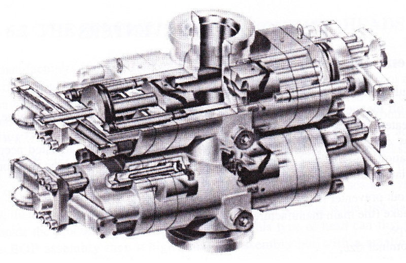 Fig. 4.1a: Double Ram - Type BOP (Source: Cameron Iron Works)
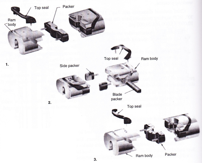 Fig. 4.1b
1. Close-up of pipe rams.
2. Close-up of shearing blind rams.
3. Close-up of variable-bore rams.
(Source: Cameron Iron Works)
4.2.2 Bag-type preventers (Fig. 4.2)
The BOPs are also called annular preventers. They can close on any piece of equipment or even on an empty borehole (not recommended). The drill string can be run in or out through the rubber packing element when the well is closed and under pressure (stripping).
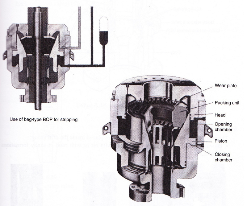 Fig. 4.2: Bag - Type BOP (Source: Hydril)
6.3.2.3 Rotating preventers (Fig. 4.3)
This type of preventer allows the drill string to be rotated and run in or out. They are placed above normal preventers and are used for drilling under pressure when low-density mud is required (when increased density would cause lost circulation). They are mainly used for drilling with air or gas as drilling fluid.
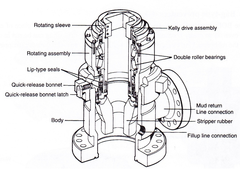 Fig. 4.3: Rotating BOP (Source: NL Schaffer)
4.2.4 Inside preventers
These are float valves and back-pressure valves placed inside the drill string:
- Downhole Baker-type valves for drilling with air or with mud in sandy formations.
- Gray Valve-type valves placed at the top of the drill string in the event of a kick during tripping and allowing the drill string to be run into the closed well under pressure.
- Back-pressure valves that are dropped from the surface and pumped to a seat located in a special landing sub placed at the bottom of the drill string (Hydril drop in-type back-pressure valve).
4.3 DIFFERENT BOP STACK COMBINATIONS
The IADC (International Association of Drilling Contractors) recommends five classes of wellheads depending on the type of duty and the working pressure of the BOPs:
| duty | working pressure (psi) |
stack |
|---|---|---|
| Light | 2000 | 2 ram-type or 1 bag-type |
| Low pressure Medium pressure | 3000 5000 | 2 ram-type and 1 bag-type |
| High pressure | 10,000 | 3 ram-type and 1x 5000 psi bag-type |
| Very high pressure | 15,000 | 3 ram-type and 1x 10,000 psi bag-type at least |
There is no recommendation on the type and respective position of ram-type BOP internal equipment. The BOP side outlets can be used instead of a mud cross.
A discussion on the position of the different rams is worthwhile to gain some insight into the different configurations and the possibilities available for controlling kicks.
With the annular preventer always placed on the top of the stack, the following describes a medium- and a high-pressure BOP stack consisting of two ram-type BOPs and a spool or mud cross. The ram-type BOPs can be pipe and blind, or shear blind.
Combinations can therefore be:
| Blind | Blind | Pipe | Pipe | |||
| MC | Pipe | Blind | MC | |||
| Pipe | MC | MC | Blind | |||
| (1) | (2) | (3) | (4) |
Advantages (in the event of a kick):
- For (1) and (2), the blind rams can be replaced by pipe rams to allow the drill string to be pulled out through the upper rams while the lower rams are kept as back up.
- For (1), if the drillpipe is in the well and a leak occurs at the mud cross (or the kill line or the choke line), the well can be closed with the pipe rams while the repair job is carried out.
- For (2) and (3), when one of the two sets of rams is closed, the MC outlets can be used to control the well.
- For (3) and (4), the well can be closed while the pipe rams are being traded for casing rams.
- For (4), a minimum number of flanges are exposed to pressure when the blind rams are closed.
- For (2), (3) and (4), when the pipe rams are closed, the MC outlets can still be used.
Drawbacks:
- For (1), (2) and (3), if the blind rams are closed, an MC leak can not be controlled.
- For (2) and (3), there are more flanges exposed when the lower rams are closed.
- For (1) and (4), if the lower rams are closed, circulation requires the use of casinghead side outlets.
The most common solutions are the following:
- with two single BOPs:
Blind Pipe MC -
with one double BOP and one single BOP:
Pipe Blind Pipe MC or:Pipe Blind MC Pipe
Here it can be an advantage to replace the lower pipe rams by variable rams.
If shearing blind rams are used, they are commonly placed above pipe rams where the drill string will hang before it is cut off. Note that the space between the two types of rams must allow a standard tool joint to rest and the cut to be made on the drillpipe body.
4.4 BOP HYDRAULIC CONTROL SYSTEMS
4.4.1 Control principles
All BOPs and the main wellhead valves are hydraulically actuated and operate according to the principle of dual-function hydraulic jacks. Each function requires one line on the opening side and another one on the closing side. Operation is based on having a supply of pressurized fluid available whenever needed for closing or opening the blowout preventers.
The following must be taken into account (for the BOP stack for a given wellhead):
- the volume of fluid required to carry out a given number of emergency open/close functions, with the specifics laid down by the operator,
- the pressure that must be exerted to get a good seal,
- the time required to close all the BOPs.
The system comprises:
- several air/oil accumulators,
- a set of hydraulic pumps,
- a direct control manifold,
- one or more remote control manifolds.
Some operators demand that all the wellhead BOPs can be closed (hydraulic pumps stopped) and that there must still be a reserve fluid supply of 50 % of the total volume at the residual pressure of 1200 psi.
Others specify a volume of fluid that can open, close and open again all the BOPs. Conditions of course depend on the degree of risk anticipated, whether standard or extreme.
The only accumulators now available on the market have a maximum working pressure of 3000 psi. BOPs operate at 1500 psi except for shear-ram preventers that cut through drillpipe and may require higher pressures depending on pipe strength.
A hydraulic regulator controlled by the driller allows him to adjust the closing pressure of the annular BOP.
4.4.2 Hydraulic unit operation
The hydraulic fluid discharged by the pumps to the accumulators compresses a bladder filled with a compressible gas such as nitrogen. There is pressure equilibrium between gas and the fluid in the accumulator. The gas acts as a spring that expels the oil when the circuit is opened by means of one of the four-way valves that selects the functions. The valves can be operated directly or remote-controlled from the rig floor.
The hydraulic pumps (pneumatic or electric) start and stop automatically according to the accumulator pressure. The main circuit is regulated at 1500 psi, but there is a specialized circuit for the annular BOP where a regulator can adjust the pressure depending on requirements (stripping in particular). The driller can also control this circuit from the rig floor.
Figure 4.4 shows the standard layout for the control unit. It must be located far enough away so that it is outside the first safety perimeter around the wellhead.
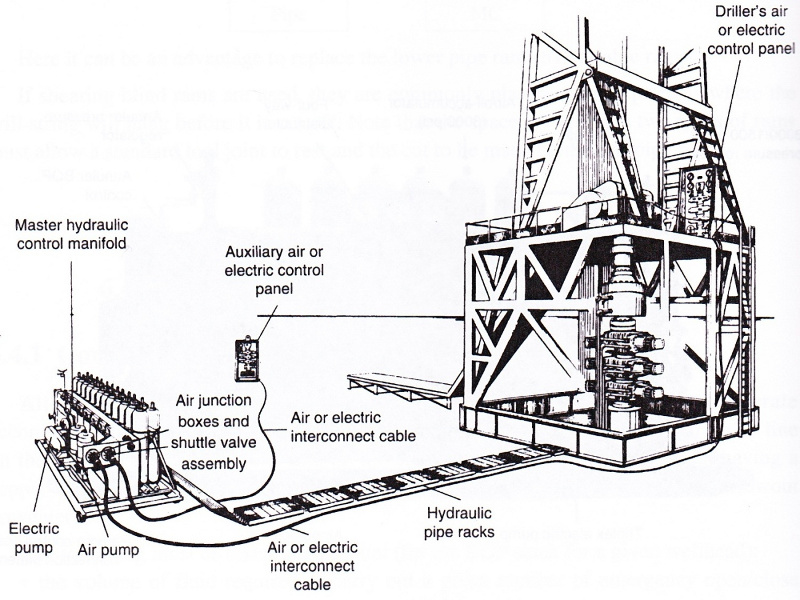 Fig. 4.4: Conventional drilling wellhead control layout (Source: NL Schaffer)
4.5 THE WELL CONTROL CIRCUIT
In order to control a kick, mud of the required density must be added and circulated while back pressure is maintained against the formation. This excess pressure must be slightly higher than the pressure of the fluids contained in the pores of the formation.
There is therefore a need for a line, the choke line, between the annulus and a manifold which directs the effluent to one of the following, depending on the type of fluid involved:
- the mud tanks,
- the degasser,
- the flare,
- the reserve pit (Fig. 4.5)
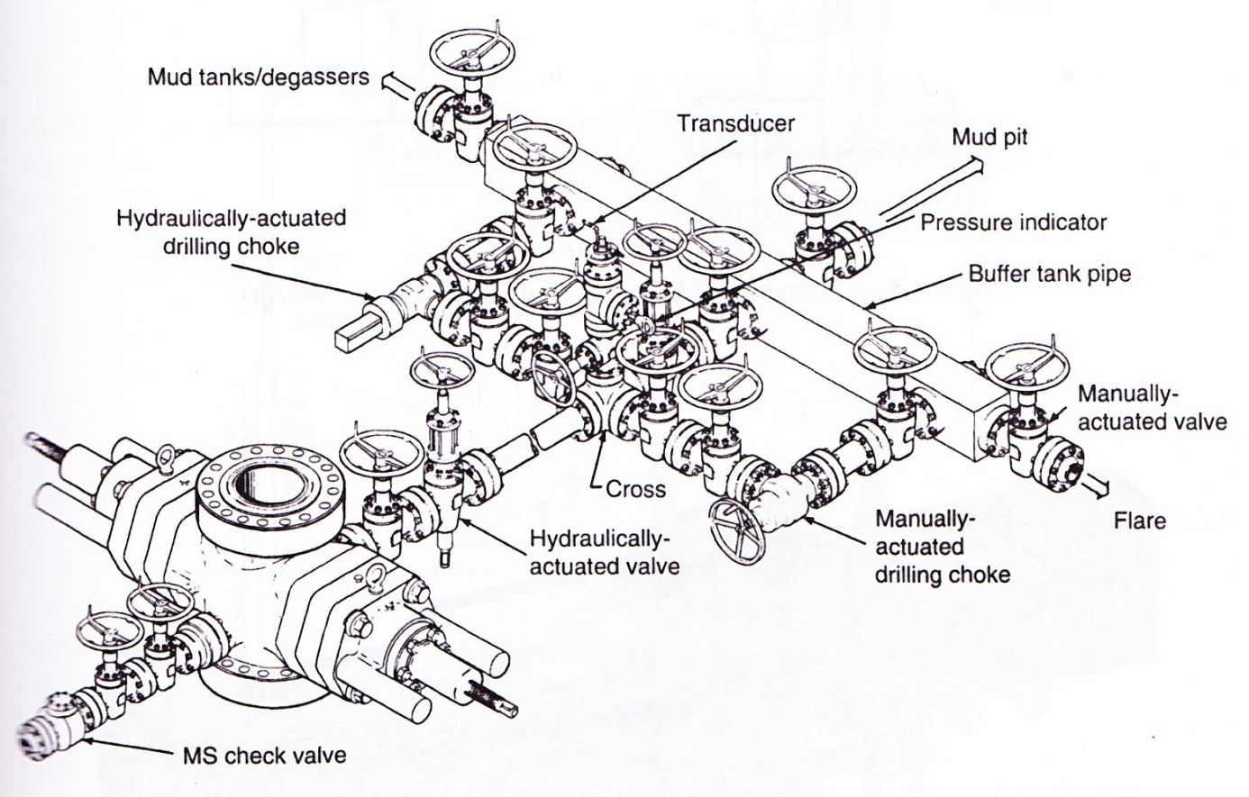 Fig. 4.5: Choke manifold (Source: Cameron Iron Works)
Since flow rates can not be regulated by plug valves, there is a set of chokes at the manifold inlet to adjust the required back pressure. There are several types of chokes:
- the positive choke, a calibrated fixed orifice used in production,
- the adjustable choke, that can be adjusted manually,
- the hydraulically-actuated choke .
It is difficult to control kicks by using the manual choke and the driller is often far from the pressure gages that show the standpipe (discharge) pressure and the casing pressure (in the annulus between the hole and the drillpipe).
There are hydraulically-actuated chokes on the market, remote-controlled from a control panel and console, with a greater or lesser degree of sophistication.
Conventional systems include:
- a fluid reservoir,
- a pump (with an air-operated motor) supplying hydraulic power,
- one or two control levers for the choke(s),
- two gages giving standpipe and casing pressure,
- a pump stroke counter,
- a pump stroke totalizer,
- a choke position indicator.
5 CASING AND CEMENTING OPERATIONS (video 6)
These two operations are indispensable to consolidate a well and are dealt with together in this chapter since the second comes systematically after the first. Generally speaking, no casing is ever run into a borehole without it being cemented in the hole.
Casing and cementing operations have a particular feature in common: any trouble during the operations may have extremely detrimental consequences on further drilling as well as on producing the well later on. This means that the operations must be worked out as carefully as possible in advance. Additionally, considerable resources must often be implemented to cope with even minor trouble immediately.
5.1 THE CASING OPERATION
Casing is the operation of running a string of pipe into a borehole that has been drilled. A special type of tubular – compared to drillpipe – is run in. It is different from drillpipe in its large diameter which leaves only relatively little clearance and its lack of mechanical strength under tensile stresses and torque. It also differs by its equipment, such as scratchers which are centralizers that increase drag. As a result, lowering casing is a tricky operation in many cases, particularly in a directionally drilled borehole. If the casing string gets stuck and does not cover all of the open-hole section, the architecture of the well as a whole is jeopardized along with the program of exploration or production operations.
5.1.1 Preparing the borehole
When the bit has reached the depth anticipated for the casing shoe, the borehole is not usually ready for the casing to be run in.
First, it is advisable to carry out logging operations. Most of them are left up to the geologist, but the drilling engineer can also request measurements that will make his job easier:
- Caliper logging to find out as accurately as possible what the volume is between casing string and borehole wall and work out the amount of cement that will be needed.
The measurement also gives useful information on zones that are calibrated to bit gage diameter where it is preferable to place the centralizers. - Azimuth and deviation measurements to get a picture of well curvature and spot the depths where sudden changes in hole angle or azimuth may hinder the casing on its way down.
- Maximum temperature measurement needs to be known to determine thickening time for the cement slurry in deep wells.
The logs listed above are automatically run along with certain operations to locate and identify formations because the measurements are needed for interpretation. For instance micrologs and microlaterologs are recorded with a caliper log, and continuous dipmetering with a continuous borehole profile log. Maximum temperature is measured at the same time as the SP-resistivity recording.
Once logging has been completed, the drill string is usually run in before casing is begun. There are two reasons for this:
- to check how well the walls hold up, and
- to circulate and possibly treat the mud.
A borehole that allows the drillpipe, drill collars and bit to pass through freely may cause enormous problems when a string of casing is run in. This is because the pipe is of a larger diameter and much more rigid than the drill string. The borehole is checked out with a rigid string and a one- or two-roller rotary reamer. If there seems to be a lot of reaming work to be done, then it will be necessary to run in several times. The driller must not forget that the more time goes by while these techniques are being applied, the more unstable the walls become.
Simply checking the borehole out with the bit may be enough in the easiest instances, only experience can tell whether this precaution is adequate.
The drilling mud can be treated when the borehole is checked. It is advisable to improve the flow properties of the drilling fluid in the borehole, i.e. decrease the plastic viscosity and the yield value, to run in deep casing strings. This will lessen the surge pressures that may be exerted on the bottom of the hole when casing is lowered and fluid is circulated in a restricted annulus.
5.1.2 Preparing the casing string
Preparation is usually done during the drilling days prior to the casing operation. The pipe is stored in the pipe yard in layers, one on top of the other (not more than three), so that the normal handling order corresponds to the planned casing string makeup.
As the pipe is brought to the well site, it is identified (grade of steel, thickness, thread) and measured. The pipe is then numbered so that each joint has been unmistakably identified. Characteristics and lengths are written down in a notebook. Then the pipe is sorted and set out in the pipe yard in lowering order. Thread protectors on both ends are removed and the joints are cleaned and greased. Only the protector on the pin end is put back on to protect the thread during handling.
Preparing the casing string also includes fitting the accessories on it (Fig. 5.1):
- the shoe and landing collar are screwed on the pipe with a thermosetting resin which sticks the joint together and keeps it from coming unscrewed when the two components are redrilled later on;
- the centralizers are fitted on the bottom of the string, level with the shoe of the previous string and above and below the staged-cementing apparatus;
- the scratchers are fitted on the bottom of the string and possibly a little higher to clean the cake off permeable sections of the borehole.
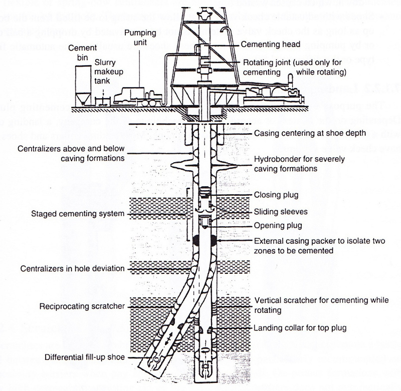 Fig. 5.1: Casing Equipment (Source: Gaz de France)
5.1.2.1 Shoes
Generally rounded, the shoe helps guide and run the casing string in the uncased part of the hole. There are several different types:
- Channel shoes with or without vents that allow the mud to go directly into the casing as it is lowered into the hole.
- Shoes with built-in check valves:
- advantages: keep the cement slurry from coming back up once it has been flushed out and prevent any blowouts from occurring through the inside of the string while the casing is being lowered into the hole;
- drawbacks: the casing string must be lowered slowly into the hole to minimize surge pressure on the formations, in addition the string must be filled from the top down, which causes wasted time.
- Shoes with adjustable check valves that allow the string to be filled from the bottom up as long as the check valve system has not been activated by dropping a ball down or by pumping at a given flow rate. These shoes are usually of the automatic fill-up type or the differential fill-up type.
5.1.2.2 Landing Collars
The purpose of the landing collar is to serve as a seat for the cementing plug(s). Depending on the context or according to the technique of the company, a landing collar with a check valve is chosen when the shoe has none. Most landing collars and shoes both have check valve systems.
The landing collar is always run in two or three joints above the shoe so that the inside volume of the string between the shoe and the landing collar can accommodate the slurry that has been polluted by the upper cementing plug scraping down through the pipe.
5.1.2.3 Centralizers
Centering the casing string is one of the parameters that govern the success of a cement job. There are centering rules for vertical and directional wells.
According to whether the centralizers are located inside casing or in the uncased part of the hole, they will be rigid or flexible:
- rigid or positive centralizers (with U-shaped blades) are designed for casing-casing annular spaces,
- flexible or spring-bow centralizers are used to center casing strings in the uncased section of the hole. There are two sorts of flexible centralizers: straight ones and spiraled ones.
5.1.2.4 Scratchers
Scratchers are designed to break down the mud cake mechanically and promote a better bond between the cement and the formation. They are particularly recommended on permeability barriers when pay zones need to be sealed off. On porous formations with fairly high permeability, getting rid of the cake with scratchers does not automatically guarantee a good cement job. Other factors can have a detrimental effect on the slurry quality (filtration, dehydration, etc.).
Scratchers are chosen according to the way the casing string will be moved during cementing:
- rotation: rotating scratcher,
- up and down: reciprocating scratcher.
A. Rotating scratchers
These scratchers are longitudinal and attached along the axis of the casing. They are metal bars covered with steel spines (scratchers) or equipped with a wire that forms spirals (wipers). They are either welded (when the grade of metal allows) or clamped between two stop rings.
B. Reciprocating scratchers
The reciprocating version is ring-shaped and is attached around the circumference of the casing either with a self-locking mechanism or between stop rings.
5.1.2.5 Hydrobonders
By modifying the fluid flow path, hydrobonders improve the displacement efficiency of the drilling fluid by the cement slurry and promote a better bond between the cement and the depth of the enlarged part of the hole. They consist of rubber disks with a diameter larger than the nominal wellbore diameter. The disks have spiraling grooves that force the slurry to circulate toward the back of the enlarged sections of the hole and fill up the cavities better. It is recommended to reverse the direction of the spirals of two subsequent hydrobonder collars if they are close to each other to get maximum alteration in the fluid flow.
5.1.2.6 Cementing baskets
This equipment is generally used to minimize losses of cement slurry in weak zones. The baskets are used only in shallow to medium depths, since they act in a purely mechanical way. They do not prevent pressure transmission but do curb fluid passage considerably. There are two types:
- the conventional model in the shape of an umbrella which is not recommended for the uncased part of the hole,
- the centralizer-basket in a one-piece apparatus, with a receptacle protected by an outside centralizer, that can be used in the uncased part of the hole as well as to move the casing during cementing.
5.1.2.7 Cementing heads
A cementing head is screwed onto the top of the casing and holds the two cementing plugs. It allows the drilling mud to circulate, the cement slurry to be pumped in after the bottom plug has been released and the top plug to be pumped down with more drilling mud.
5.1.2.8 Cementing plug
The plugs are mainly designed to separate the different fluids (mud, intermediate fluid, slurry) physically while they are being pumped through the casing. The plugs keep the fluids from mixing for as long as possible and lessen contamination risks. There are two types of plugs:
- The bottom plug has a membrane that bursts when a slight overpressure is exerted. Though optional, it is strongly recommended. Besides separating the fluids, the bottom plug scrapes the walls as it moves down through the casing. As a result, it helps keep the slurry behind it from becoming overly contaminated.
- The top plug is designed to provide a seal and to withstand high pressures. It is mandatory and pumped in on the tail end of the slurry. When the slurry has been flushed out the plug comes to rest on the bottom plug (or on the landing collar) and then allows pressure testing to be performed on the casing string.
5.1.2.9 Specific equipment for two-stage cementing
Primary cementing equipment is standard, but for second-stage cementing, a stage float collar or DV (diverter valve) must also be incorporated in the string. The DV serves as a bypass between the inside of the casing and the annulus so that the cement can be circulated and flushed through the annulus at the selected depth.
When primary cementing has been completed, the DV is opened by pressure applied on the bomb that plugs off the lower sleeve. The second stage can then be cemented. Then a closing plug is released to move the upper sleeve downward at the end of the flushing phase that closes the ports.
5.1.2.10 Liner cementing equipment
Liners are equipped the same as for primary cementing with a subsea wellhead, but they are hung in the preceding string by what is called a liner hanger. There are two types of liner hangers:
- mechanical: (J slot) a longitudinal rotating movement unlocks the locking wedges and makes them grip inside the casing,
- hydraulic: releasing a ball and exerting hydraulic pressure move a sleeve that activates the gripping process.
5.1.3 Lowering the casing
The casing must be lowered as fast as possible, since the time spent is nonproductive the same as any running in or pulling out operation. The casing string lowering speed must be controlled according to the surge pressures generated on the bottom and the walls of the hole. The work needs to be well organized, since any stopping on the way down because trouble has arisen may well cause the casing to get stuck at that depth.
The handling principles are the same for casing and drillpipe, but the equipment is adapted to casing diameters and to the lower collapse strength. A spider and a casing elevator are often used.
The lengths of casing are screwed together by means of hydraulic tongs. A service company is often used for this difficult operation.
The driller monitors the casing string as it is being filled if need be and keeps track of the hydrostatic level in the well. Once the casing has been run in, the mud can be reconditioned and circulated while the string is being maneuvered to put the scratchers to work. Circulation will be stopped only when:
- the mud returns no longer contain cuttings
- the gas content is low and constant,
- there are no lost returns or kicks,
- the total volume of circulating mud is homogeneous.
As the casing string is equipped with the cementing head and plugs, the cementing operation itself can begin.
5.2 THE CEMENTING OPERATION
Cementing operations consist in placing an appropriate cement slurry in the annulus between the walls of the hole and the casing that has been run in.
There are several types of cementing jobs and each one meets a particular need:
- Cementing casing strings for a number of purposes:
- isolating a producing formation from adjacent beds,
- securing the casing mechanically to the borehole walls,
- protecting casing from corrosion by fluids contained in the beds that have been drilled,
- providing a leak-proof base for safety and control equipment that is installed on the wellhead.
- Cementing under pressure, called squeeze cementing, in cased and perforated boreholes, also for a number of purposes:
- injecting extra cement through the perforations in the casing to consolidate or repair the primary cementing job,
- sealing off a depleted productive layer,
- isolating a bed from adjacent zones to reduce the per cent of water or gas in oil production.
- Placing cement plugs in an open hole during drilling in order to:
- seal off water influxes,
- plug up lost circulation zones,
- serve as the basis of a side track,
- comply with well abandonment procedures.
5.2.1 Principles of cementing methods
The aim is to force a cement slurry into the annulus between the outside of the casing that has been landed in the well and the walls of the borehole. The slurry is pumped directly down the casing that is going to be cemented or through drillpipe. It is then pushed up in the annulus between the casing and the hole to a predetermined height.
The slurry is usually mixed continuously on the surface two pressurized water jet mixers that wet the cement in powder form and convey it to a small surge tank where the slurry density is checked constantly. It is then sucked up by high-pressure piston pumps and pumped into the well.
The slurry density is adjusted by varying the flow rate of the water that comes into the system downstream from the point where the dry cement and the mixing water meet.
Dry cement is fed into the system by gravity from a silo, the cement bin. Modern-day equipment has forced-air feed with the cement piped to where it comes into contact with the mixing water. This setup is typical offshore.
5.2.1.1 Primary cementing
Cement slurry is pumped into the well, flows through the shoe and then starts flowing up through the annulus. The landing collar, as its name indicates, serves as a shoulder for the bottom and top wiper plugs that respectively precede and follow the slug of slurry in the casing (Fig. 5.2).
A pressure surge ruptures the bottom plug and allows the slurry to pass through and circulate up into the annulus. It is the slurry that displaces the drilling mud directly while at the same time „washing“ the borehole wall and the outside wall of the casing as it flows by. When all the slurry has been pumped down, the top plug is released and is pushed along down by the drilling mud. This operation is called flushing and the flush volume is the volume of drilling mud between the landing collar and the cementing head. When the flush has been completed, a pressure increase is seen as the top plug bumps against the landing collar.
The overpressure can be held steady for a few minutes in order to test the seal on the casing string at the same time.
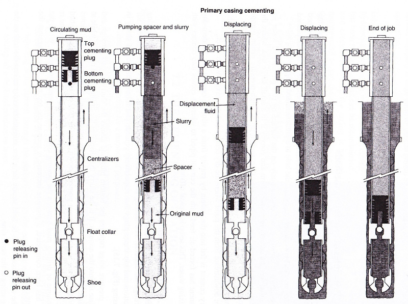 Fig. 5.2: Principles of primary cementing procedure
(Source: Dowell Schlumberger)
5.2.1.2 Stage cementing (Fig. 5.3)
The string is equipped with a DV at the predetermined depth. A primary cement job is done in the routine way with, however, the diameter of the cementing plugs selected so they can pass through the cross-section narrowed down by the DV. After the pressure surge, the bomb is dropped (50 to 60 m/min depending on the deviation). The opening pressure (around 10 MPa) Shears pins and moves the sleeve so that the slurry can then be pumped in, but no bottom plug is used. Once the slurry has been pumped in, the top plug is released and flushed down to the DV. The top plug then closes the DV by moving a second sleeve.
 Fig. 5.3: Principle of two-stage cementing (Source: Dowell Schlumberger)
5.2.1.3 Cementing liners (Fig. 5.4)
A liner goes up to a limited height inside the preceding casing, not all the way up to the wellhead. It is cemented with an overlap inside the last casing.
A liner is cemented for two reasons:
- to bond it mechanically to the preceding string,
- to ensure a good seal between the liner and the string.
The best odds of getting a good cement job for the top of the liner dictate an overlap of 80 to 150 meters depending on the diameters. In addition, the liner is often the last tubular set in the well. It is cemented at the depth of producing formations and then perforated to bring the well on stream selectively. It is therefore important to have a high-quality cement job so that the different levels of the reservoir can be isolated and unwanted influxes (water, gas) can be minimized.
A production casing may be connected to the top of the liner by a tie-back. Liners fulfill the functions of conventional casing, but are used instead of a complete string:
- to reduce costs of: pipe, running time, wellhead components, small-diameter drill string (combination string),
- to use a larger tubing diameter,
- when the wellhead does not allow a given-diameter string to be anchored.
Depending on how liners are set, a distinction is made between two types:
- Liner set on the bottom. This method is used less and less as it affords little safety. It means there is a limit on the length of the string that is set under compressive stress.
- Suspended liner. The trend was to run in longer and longer casing with increasingly large diameters. This led to the use of liners hung in the casing already in place in the well.
Circulation equipment includes only one plug attached to the top of the liner on the extension of the running tool. An initial plug adapted to the drillpipe diameter displaces the slurry in the drillpipe. When this plug bumps the liner plug and fits into it, the two together flush the slurry in the liner to the landing collar.
The driller then unscrews the running tool by turning it to the right and proceeds to reverse circulation to clean the excess slurry from the upper part of the liner hanger.
 Fig. 5.4: Principle of the liner cementing procedure (Source: Dowell Schlumberger)
Reverse circulation is achieved by closing a BOP on the drillpipe and using the kill-line to inject mud into the system. The mud returns up through the drillpipe.
5.2.1.4 Squeeze cementing
This operation involves placing a cement slurry under pressure in a given location in the well. The purpose is to repair a defective seal or produce a new seal (to plug up perforations of a depleted bed). Pressure is exerted on a permeable formation so that the slurry loses water gradually and forms a cement cake. The cake sets and fills in any gaps in the seal or plugs up lost circulation zones.
The slurry is usually injected by the „hesitation squeeze“ method. This involves stop and start pumping of batches of a few hundred liters of slurry, with pumps cut off for a few minutes and then on again and pressure increasing gradually until the final squeeze pressure is reached.
5.2.1.5 Positioning plugs of cement
Here a given amount of cement slurry is placed in the uncased part of the hole or in a string with the drill string by simple circulation.
There are a number of reasons for this type of operation:
- to abandon a well by isolating permeable formations and final closing procedure with a cement plug at the casing shoe,
- to close off an aquifer,
- to make a seat for a well to be resumed with directional drilling or a seat for a test drill stem,
- to plug up lost circulation zones,
- to abandon a depleted reservoir before bringing a shallower pay zone on stream.
The drill string or tubing string is used as the common way to spot the plug. The amount of slurry required to fill up the planned height is made up and injected, then flushed out until the column of cement inside the drill string balances the column outside. The drill string is then pulled out.
The same as for other types of cement jobs, some specific precautions must be taken.
The height to be covered depends on the required effect. If the aim is a seat for a sidetrack, the plug usually has enough height (about a hundred meters) so that several attempts can be made one after the other. In small-diameter wells, the height can be quite considerable, because little height would mean such a small volume of slurry that is would be extremely difficult to spot the plug properly.
Either ordinary or retarded cement is used depending on the plug´s final depth and all the conventional additives may be added. However, bentonite is not recommended, as it decreases the slurry´s compressive strength. For operations at shallow depths where setting time is very long for straight cement, calcium chloride is used as a cement setting accelerator. Sand, added at 5 to 20% by weight of straight cement, reinforces the cement´s mechanical strength when the aim is to build a seat for a sidetrack. It also increases the density of the cement slurry.
The plugs are preferably placed where the borehole is well calibrated or at the permeable zones they are designed to seal off.
When a sidetrack is being prepared, the upper part of the plug will be placed where there is a relatively soft formation to make the job easier.
The drill string or tubing string is first run in to the required depth for the bottom of the plug. Circulation is begun and continued until the mud density is the same all throughout the system.
The slurry must be made up fairly slowly and care must be taken to use a minimum amount of water and get a good homogeneous mix. Since a small amount of cement is usually needed, cement in bags is used.
The volume of slurry to be pumped must be calculated and measured carefully. The principle is to wind up with equal heights of cement inside and outside the drill string at the end of the pumping phase. If a caliper log has been run, accurate calculations can be made. If not, the actual diameter of the hole – always a little larger than the bit – must be estimated.
Immediately after the volume of slurry has been pumped down, the drill string is pulled out slowly. When the upper part of the plug must be located at a given depth, a volume of slurry is used that is greater than the volume of the height that is to be covered. Then drilling mud is circulated, usually in reverse circulation, at the predetermined depth to flush out the excess cement slurry.
Setting time is chosen according to downhole conditions and to the final mechanical resistance required for the cement plug.
The plugs used to prepare a well for abandonment are checked after approximately 24 hours have elapsed. The first few meters, always contaminated by drilling mud, are redrilled and the rate of penetration is recorded. When the drilling rate falls between 5 and 10 m/h, the cement´s strength can be considered satisfactory. The final check consists in landing between 10 and 15 tons on the bottom with circulation.
It is always a difficult operation to place a strong, leak-proof plug of cement. Factors influencing its success are: careful choice of the zone to be covered, exact calculation of the volume to be pumped into the well and accurate on-site measurements, use of wall scratchers to help the cement bond, choice of additives for straight cement (sand, cement accelerator), and slow, steady handling of the drill string once the cement is in place.
5.2.2 Choosing the cement slurry
The choice is governed by:
- the static temperature downhole, which conditions setting time and therefore the thickening time,
- the circulating downhole temperature while the slurry is being pumped down as it modifies the setting time and therefore the thickening time in a positive sense,
- the slurry density required by the hydrostatic pressure limitations of some of the drilled formations,
- the plastic viscosity of the slurry and its filtration characteristics,
- the rheological parameters of the slurry,
- the setting time and the time it takes the slurry to develop compressive strength,
- the way the cement withstands a number of agents likely to deteriorate it, e.g. some types of corrosive water and high downhole temperatures.
Commonly used slurries are made up chiefly of cement and water with one or more additives, each with a given function. However, some additives counteract the action of others, creating compatibility problems among them. Slurries are laboratory-tested under conditions that simulate actual on-site conditions and downhole environments.
There are a variety of cement categories, defined by API standards, according to the depth and mainly the downhole temperature of the well. Another determinant is the likelihood of contact with corrosive formation waters. The cement types are as follows:
API Spec 10
| Class | Type |
| A | For use from surface to 1830 m (6000 ft) depth when special properties are not required. Ordinary type. |
| B | For use from surface to 1830 m (6000 ft) depth when conditions require moderate to high sulfate resistance. |
| C | For use from surface to 1830 m (6000 ft) depth when conditions require high early compressive strength. Available in low, moderate and high sulfate-resistant types. |
| D | For use from surface to 1830 m (6000 ft) to 3050 m (10000 ft) depth under conditions of moderately high temperatures and pressures. Available in moderate and high sulfate-resistant types. |
| E | For use from 3050 m (10000 ft) to 4270 m (14000 ft) depth under conditions of high temperatures and pressures. Available in moderate and high sulfate-resistant types. |
| F | For use from 3050 m (10000 ft) to 4880 m (16000 ft) depth under conditions of extremely high temperatures and pressures. Available in moderate and high sulfate-resistant types. |
| G | For use from surface to 2440 m (8000 ft) depth as manufactured, or can be used with accelerators and retarders to cover a wide range of well depths and temperatures. Available in moderate and high sulfate-resistant types. |
| H | For use from surface to 2440 m (8000 ft) depth as manufactured, or can be used with accelerators and retarders to cover a wide range of well depths and temperatures. Available only in moderate sulfate-resistant types. |
| J | For use from 3660 to 1880 m (12000 to 16000 ft) depth under conditions of extremely high temperatures and pressures. Available only in sulfate-resistant type. |
5.2.2.1 Cement characteristics
Manufacture
Artificial Portland cement is produced by calcining at over 1400°C a mixture of calcarious and argillaceous materials mined in quarries. The two basic materials are ground and fed into a rotating furnace. The combustion product, called clinker, is cooled and stored before being pulverized. It is pulverized with a number of added materials such as gypsum, but also natural or artificial pozzolan and blast furnace slag, etc. The pulverized, screend, ready-to-use product is delivered to well sites in bags or in bulk.
The resulting cement is a complex mixture whose basic components are silica, calcium, aluminum and iron. Its mineralogical composition varies within a given range and is defined as a state of equilibrium among different theoretical compounds. It is obtained by calclulations based on a mineralogical analysis. The compounds are as follows:
- tricalcium silicate C3S
- dicalcium silicate C2S
- tricalcium aluminate C3A
- tetracalcium ferroaluminate C4AF.
5.2.2.2 Cement hydrating mechanisms
When cement is mixed with water it becomes hydrated starting with the less stable anhydrous components. They are dissolved to saturation more readily than the more stable hydrated components. When there is insufficient water, the solution is supersaturated with respect to hydrated components which crystallize. This allows the anhydrous components to dissolve once again. Gradually, the crystalline needles will become bonded together until the whole system hardens.
The first component that reacts is the C3A which gives a calcium sulfoaluminate with the gypsum. This is what will determine how quickly the cement sets according to the composition of the aqueous phase, i.e. the equilibrium conditions of the soluble salts, hydroxides and other products that are normally or accidentally found in solution.
The C3A that has not reacted with the gypsum is hydrated singly and subsists in this form in the hardened cement. However, if sulfates are prosent later on in water infiltrations, a C2 sulfoaluminate is formed with an increase in volume. The reaction breaks up the crystalline network and destroys the continuous structure of the cement. This preliminary hydration phase is very important in oilwell cement jobs since it corresponds to the thickening time of the slurry when it can still be pumped.
A number of factors influence cement hydration.
A. Temperature
Temperature has a great influence on cement hydration speed. Higher temperatures will shorten setting time by accelerating hydration speed.
B. Pressure
By modifying the equilibrium conditions in the liquid phase, increasing pressure speeds up hydration.
C. Contamination
Contamination is a phenomenon with random effects it may be due to the water when the cement is being mixed or to fluids encountered in the well when the cement is being pumped into place.
Any modification in the equilibrium of the aqueous phase by unwanted additions of soluble or insoluble materials affects cement hydration. As a result, the thickening time and final strength, etc. are also affected.
Sodium hydroxide, sodium carbonate and sodium silicate cause acceleration. However, it should be noted that the acceleration is totally unpredictable and often has disastrous consequences on the final cement quality.
Sodium hexametaphoshate and acid sodium pyrophosphate (drilling mud additives) have even more erratic effects, either accelerating or retarding depending on the concentration. Sodium chloride also has the same accelerating or retarding effect depending on the concentration.
Other contaminants act at the liquid phase-solid phase contact area level. Examples are starches, tannins, cellulose derivatives, lignosulfonate acids, and carboxylic acids. These products in solution are adsorbed on the cement particles and form a leak-proof barrier that retards hydration. It may even keep the cement from setting at all when contamination is substantial.
Using spacers helps overcome the drawbacks of contamination.
7.2.2.3 Cement additives (Table, Fig. 7.18)
Accelerators
These products speed up cement setting at low temperature of offset the retarding effects of other additives. They help shorten waiting-on-cement time before drilling operations can be resumed.
Retarders
These additives slow down cement setting and thereby lengthen thickening time for pumping the cement into place. They are used when high downhole temperature or the accelerating effect of another additive might dangerously reduce the time available for pumping the cement.
•
(1)
Denotes major effect and/or purpose of additive
Carboxymethyl hydroxyethyl cellulose
(Source: Drilling Data Handbook, Editions Technip)
Extenders
These are lightweight, inert materials mixed with cement and designed to reduce both slurry density and costs. However, most lightweight additives have an effect on cement setting time and compressive strength. Special additives are often necessary to offset this tendency.
Fluid-loss additives
These agents stop the slurry from losing water by filtration into permeable formations. Water loss may trigger either unwanted setting or no setting at all since not enough water is available for hydrolysis and crystallization of the cement components.
Heavyweight additives
These products serve to increase slurry density. They are inert mixed in with the dry cement.
5.2.2.4 Miscellaneous agents
- Dispersants offset an overly-high viscosity and some slurries´ tendency to gel. They also help establish turbulent flow when it is needed.
- Antifoam agents prevent the excessive foam that is produced when some cements are mixed. Foaming can interfere with smooth pump operation.
- Gelling agents modify the thixotropic properties of some slurry.
- Liquid additives can be added to the mixing water instead of being incorporated dry into the cement before it is hydrated.
5.2.2.5 Spacers
The spacer fluid on the leading edge of the slurry is designed to:
- make it easier to move the mud through the annulus,
- isolate the cement slurry from any contact with the mud so that the mud does not gel,
- make it easier to get rid of mud that has gelled on the walls of the casing.
The calcium present in cement causes the argillaceous particles in drilling mud to flocculate out and this in turn causes slugs of highly viscous mud to be formed. The slugs may be channeled by the cement, resulting in a poor cement job. Spacers act mainly as a „cushion“ to prevent contamination of the mud by the cement.
5.2.2.6 Choosing the type of flow
Laboratory results and experience show that slurry moving in turbulent flow achieves a 95% displacement of the mud. Displacement by slurry in streamline flow is much less effective.
Research into cement slurries focuses particularly on two characteristics: thickening time and rheological properties.
A. Thickening time
This is an empirical criterion that makes it possible to determine how long the cement slurry will be pumpable by the equipment on a well site under real conditions of use. Determining the thickening time involves a viscosity measurement defined by an arbitrary scale graduated in units of consistency (UC) from 0 to 100. By definition, the limit on utilization is 100 UC. The measurement is made in an apparatus that simulates real pressure and temperature conditions. Testing is done at a temperature, termed circulating temperature that is determined on the basis of the static temperature. Static temperature is the temperature of the well when it is in thermal equilibrium with the environment.
B. Type of flow and rheology
It is necessary to consider the characteristics (density, rheology) of the drilling mud already in the well before the cement job is done. The fluid that is most readily displaced by the cement slurry is water. Any increase in the density or rheology of the drilling mud will have a negative effect on displacement by the slurry. So that displacement defects can be minimized, the density and rheology of the slurry need to be properly adjusted taking the mud characteristics into account.
To prevent any contamination of the slurry that would be detrimental to the cement job, a spacer fluid is run in between the mud and the slurry (see paragraph 5.2.2.5). The spacer will also have density and rheology characteristics such that it can:
- displace the drilling mud,
- be displaced by the cement slurry.
Adjustments involving density, rheology and annular velocity are made so that one fluid can be more readily displaced by another in an annulus.
Regulating the density
In an initial approach, the following rules can be used as a basis:
The drilling mud has a density governed by drilling conditions and equal to dmud:
- the density dspa of the spacer fluid will be such that:
dspa = dmud + 0,1 - the density ds of the slurry will be such that:
ds = at least dmud + 0,4
Adjusting the rheology and the annular velocity
These two parameters are closely related. The fluids involved in cementing (drilling fluid, spacer fluid, cement fluid) are usually non-Newtonian. They can be characterized by Bingham plastic or power law rheological models. Depending on the geometry of the annulus and the flow rate, each one of these types of fluid moves respectively in the following type of flow: plug, laminar and turbulent.
The best displacement of one fluid by another occurs when the second fluid has a flat velocity profile. The aim for the cement slurry is therefore either plug or turbulent flow in the annulus. In turbulent flow, the energy supplied by eddies can only be beneficial in displacing the fluid preceding the slurry.
5.2.3 Implementation
Cement is delivered to the user in bulk or bags, with bulk delivery preferred. But in the oil industry, distribution in bags has been the rule for so long that the bag has become a unit of measurement. Here the bag is standard at 94 lbs with a volume of one cubic foot.
However, the bag usually goes no farther than the supply base. It is in bulk that the cement is taken out to the well site after the different dry additives have been mixed in.
The cementing operation itself is performed by a cementing unit that includes all the equipment and materials required to emplace the cement (Fig. 5.6):
- one or more tanks to ensure an extra supply of water is on hand for mixing,
- one or more centrifugal pumps to supply the tanks, mix the fluids and boost the high-pressure pumps,
- a mixing apparatus for the cement,
- one or two high-pressure pumps,
- monitoring and measurement equipment.
 Fig. 5.6: Truck-mounted unit
(Source: Halliburton)